|
|
|
|
|
|
MRL 1-TUBE DX ALL WAVE RECEIVER |
|
|
|
|
|
|
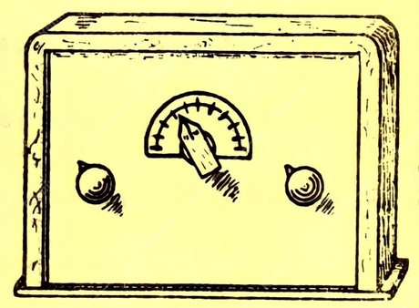
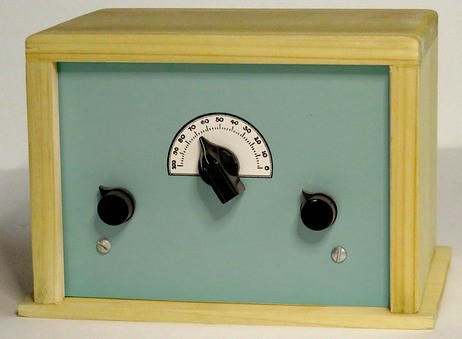
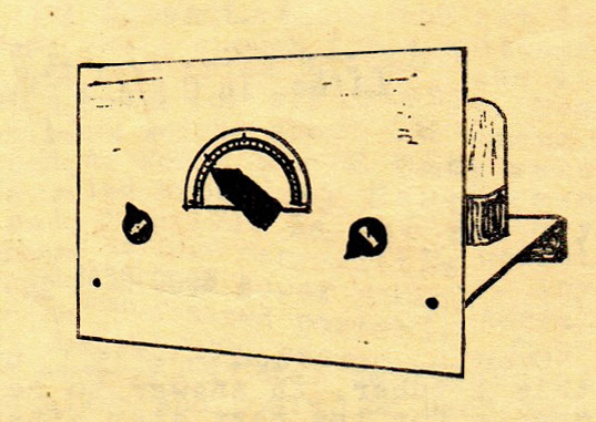
On the left, MRL 1 Tube Radio rendering from the inside cover of
MRL Detail Print File Number 2, which was a copy of the drawing from MRL Radio Builder # 19 dated 1941.
According to HB-5, Crystal Set Construction (©
1956), MRL used to sell
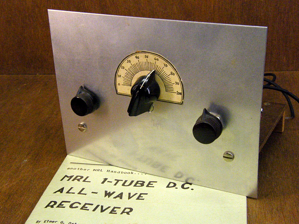
the cabinet shown in the drawing. Reproduction of the radio in a
similar cabinet was made in 2021. |
|
|
|
|
|
|
|
|
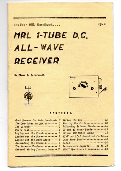
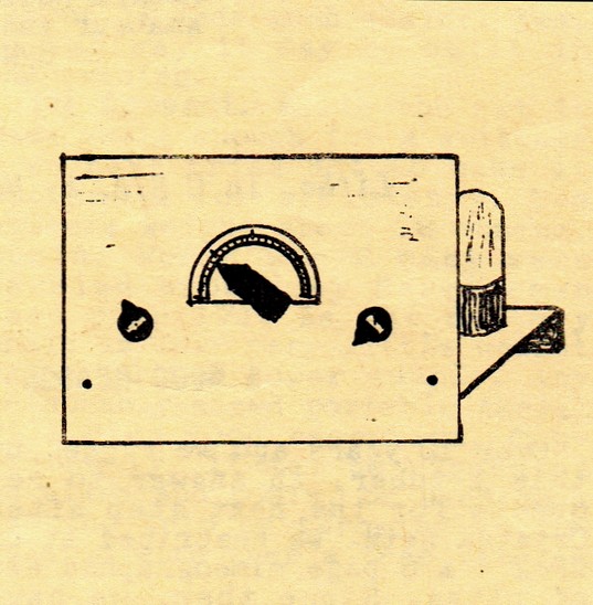
Here's the cover of HB-4 from 1953. This is one of the very few drawings
Elmer made that has any perspective.
However, this doesn't actually have real perspective. The front
panel is a perfect rectangle. |
|
|
|
|
|
| All he had to do was close one eye and
look at the radio, but as mentioned earlier, without these
unique drawings Elmer's catalog and handbooks wouldn't have
quite the nostalgic appeal they have today. |
|
|
|
|
|
|
Left knob controls the antenna tuning; the knob on
the right is the regeneration control. |
|
|
|
|
|
|
|
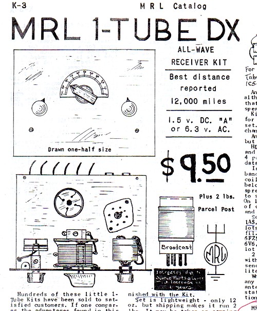
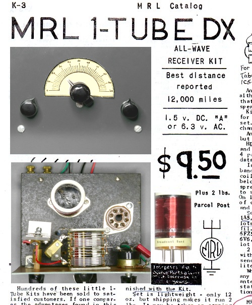
Catalog entry for the MRL 1 Tube DX radio.
Click on picture for the full catalog
page.
|
In 1940 Elmer developed the MRL 1
Tube regen radio. The circuit is a typical regen but Elmer
claimed he perfected the layout of the parts.
He made a six page mimeographed "blueprint" named BP-2 which
described the radio. After selling thousands of these
the stencils disintegrated.
In 1954 he published HB-4, "MRL 1-TUBE D.C.
ALL WAVE RECEIVER." The handbook describes every aspect of
the radio and how to make every part of it. All data is
included for making the plug-in coils.
|
|
|
|
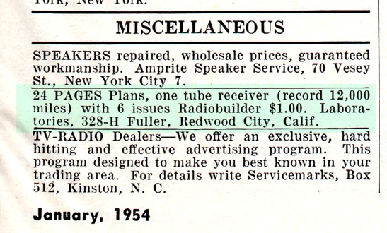
This is an ad in Radio and Television News for
plans to build the MRL 1 Tube radio.
The ad ran in January and March of 1954. Since the audience of the
magazine was
mainly
television repairmen and technicians, it probably didn't generate
many sales.
|
|
| Why gather all the parts and make the coils when you can
just buy the kit from MRL? The kit came with two coils for
the AM broadcast band but you had to buy the tube
separately. Most tubes were $1. If you didn't want to build
the kit, Elmer would build it for you for $3. |
|
|
|
|
|
|
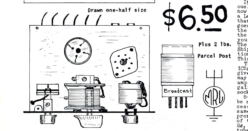
At the time HB-4 was published, the price of the kit was $6.50.
In 1946 the price was $4.95.
$4.95 in 1946 is equivalent to about $78.00 in 2024 |
|
|
|
|
|
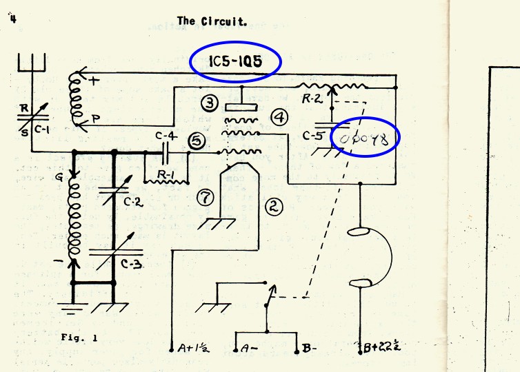
The first 1000 copies of the
handbook had the tube type omitted. After some inquiries by
customers, Elmer made a rubber stamp and stamped the
remaining copies. The later printings included the tube type, but he changed the value of C-5 from .0001 to
.00048. This change was written in ink.
If you have a copy of HB-4 with no tube type listed on page
4, or a copy with the type stamped onto the page, it is
quite a collectors edition (but nobody knows it). |
|
|
|
|
|
|
| Oddly, this circuit was
obsolete at the time Elmer printed the Blueprint in 1940. As a matter of
fact, the manufacture of this type of radio had been banned sometime
before 1924 and they were only obtainable as a kit. One tubers (sometimes called "Bloopers") can oscillate through the antenna
and wreak havoc with other radios. |
|
|
|
|
|
|
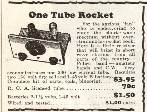
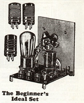
Crops from typical ads in 1934 for a 1 tube radio. Elmer never
included a picture in any advertisement.
Notice the left one only picks up shortwave. It has a "blueprint," like Elmer's early radio plans.
|
|
|
|
So why did Elmer create this kit in 1940? This is purely
conjecture, but 1930s radio magazines had many advertisements for one tube radio
kits. By 1940 the ads had practically disappeared. That
would make competition for MRL's one tube set almost
non-existent.
The MRL 1 Tube radio works well, but requires patience
to tune. Like a crystal set, it requires a set of high
impedance headphones, also available from MRL. |
|
|
|
|
|
|
| Other MRL 1 Tube examples
are
|
here |
|
|
|
|
|
|
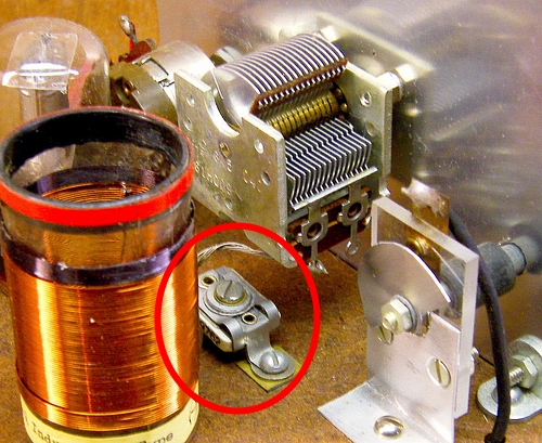
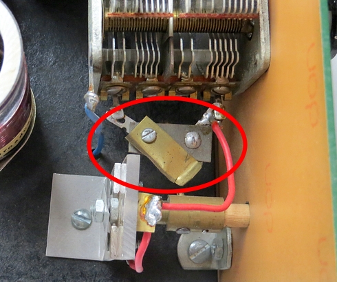
Here you can see one of the changes made
during the years. In 1952 Elmer could no longer obtain 140 pF
variable capacitors, so he used a trimmer in series with a 350
pF cap. Notice the trimmer on the left is also shown in the
drawing at the top of the page.
Later, he obtained two-section capacitors. He added an
MRL-made switch to switch one of the sections in or out. The
switch is closed for the AM broadcast band and open for
shortwave. |
|
|
|
|
|
|
|
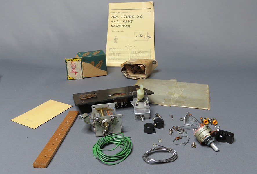
An unassembled MRL 1 Tube kit from 1980. |
|
|
|
|
|
|
|
|
|
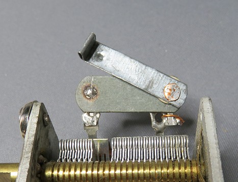
MRL antenna tune capacitor. |
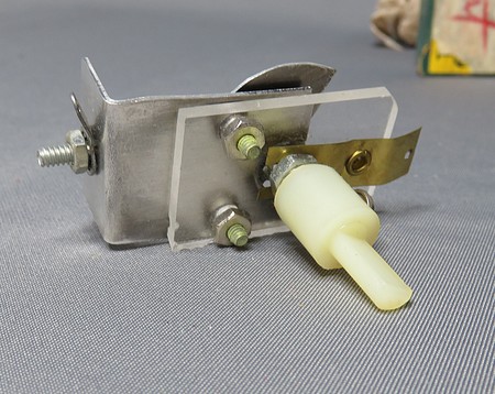
MRL switch. |
|
|
|
|
|
|
|
"Compo." base with parts mounted by Elmer Osterhoudt. |
|
|
|
|
|
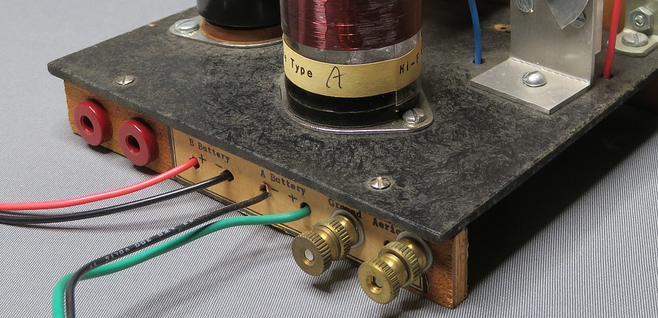
Elmer mounted the sockets because people were putting them in
backwards. |
|
|
|
|
|
|
|
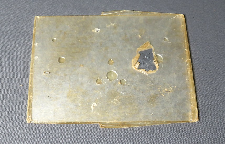
| Elmer (or Mabel) wrapped the front panel
in waxed paper. Something has gone through the paper and
scratched the panel. No worries; in the instructions Elmer says to
sand it and paint it. |
|
|
|
|
|
|
|
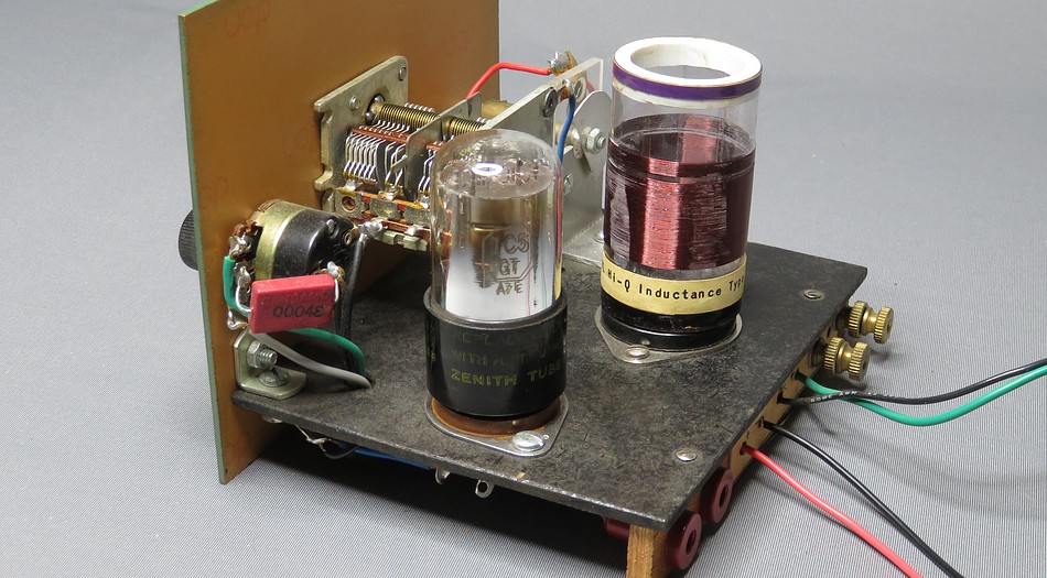
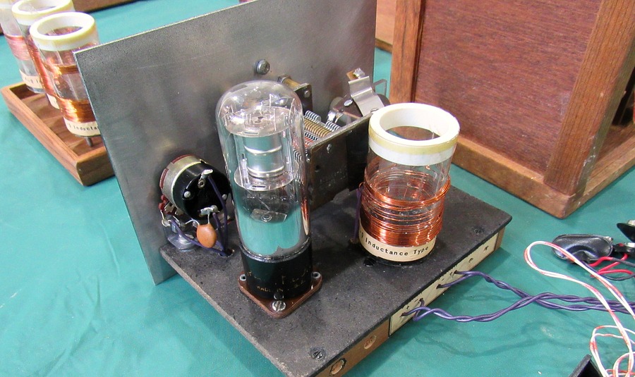
This set was built by Doug Wilson in 1982. The vacuum
tube is a 1C5-G. |
|
|
|
|
|
|
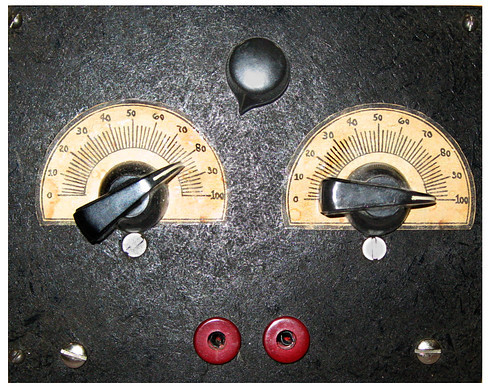
Several MRL sets have been found with this type of
dial scale instead of the hand drawn one. |
|
|
|
|
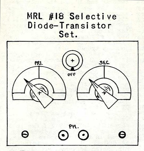
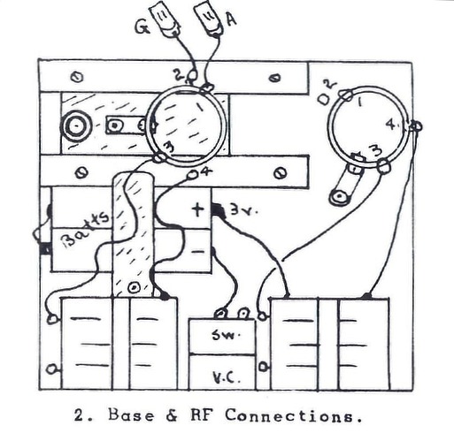
MRL #18 DIODE-TRANSISTOR SET |
|
| |
|
|
| |
|
|
| Photo Thanks to
Graeme Zimmer. Click for larger
version. |
|
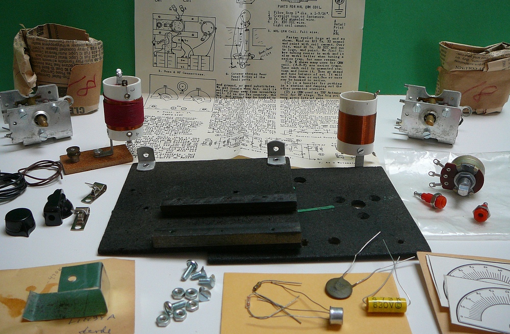
| An unassembled MRL No. 18 Diode -
Transistor Kit. You'll have to assemble it in your mind, like Nikola Tesla
would do. |
| |
|
|
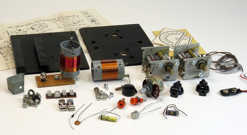
| Here's another MRL No.18 kit. It
dates from 1982. |
| |
|
|
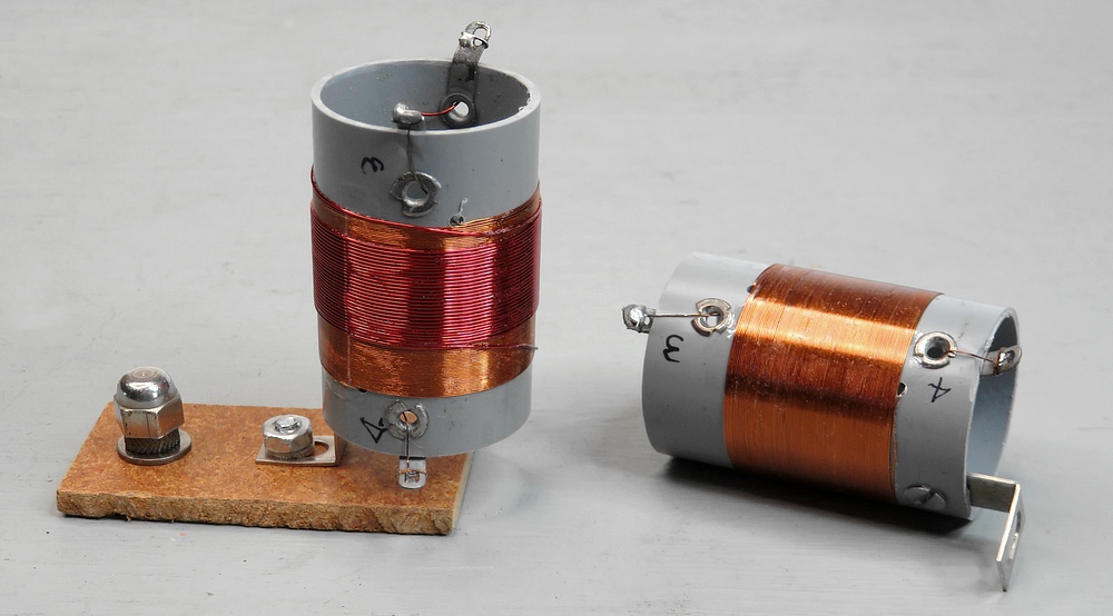
Coils to the No.18. The one on the
left looks like typical MRL QRM coil, however the secondary has 30
turns instead of 15. On the right is a QRM coil without
the second winding. In operation, the left-hand coil slides in a
track. As it comes into proximity with the right-hand coil
the selectivity of the receiver changes.
The transistor seems to be a General Electric 2N1098 audio
amplifier. They were sold in the 1973 through 1986 MRL catalogs for 99¢. |
|
| |
|
|
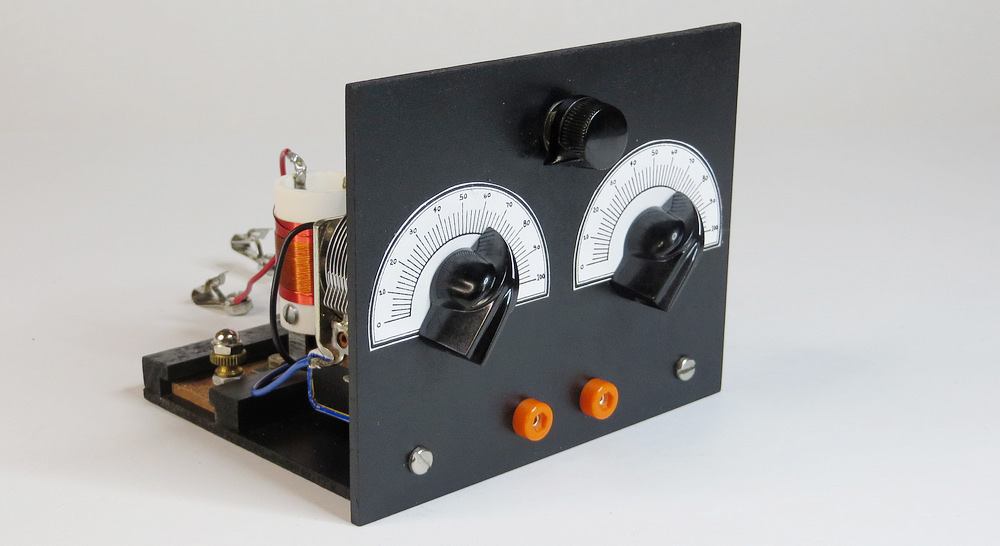
| MRL No. 18 replica, assembled in
2025. |
| |
|
|
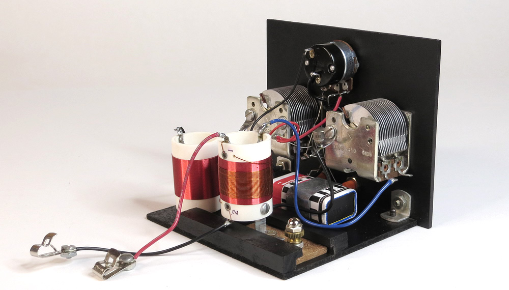
| MRL No. 18 replica, rear view. |
| |
|
|
| An actual No. 18 built in 1980 by
Sloane Freeman. |
| |
|
|
MOTHER EARTH NEWS - 1979 |
|
| |
| |
In the May / June 1979 issue
of "The Mother Earth News," Copthorne MacDonald wrote an
article on crystal sets and listed MRL as a source for
parts, and more specifically, the MRL No.2 Crystal Set.
In a letter from Elmer Osterhoudt to MRL customer Sloan Freeman, dated July 12, 1979, Elmer wrote that because of
the article he sent out over 500 catalogs, and he had
never sold so many crystal sets. Some people
wanted the assembled kit, and he still had 19 sets waiting
to be wired up at the time he wrote the letter.
It is interesting to see that the address for MRL begins
with "DEPT TMEN." Of course, that would be short for The
Mother Earth News, so EO seems to have been consulted before
the article was published. He could then track how many
orders resulted from the article.
Elmer was 80 years old at the time.
Click on the article to open a readable version |
|
|
|
|
| |
|
|
| |
|
|
| |
|
|
| This shows one example of how they
were used. |
| |
|
|
| |
|
|
| |
|
|
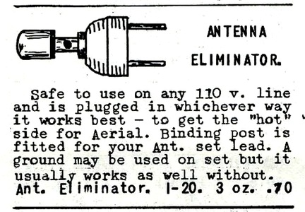
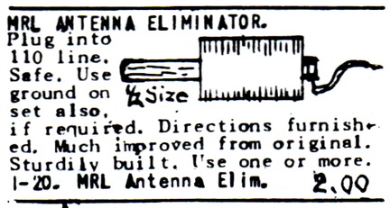
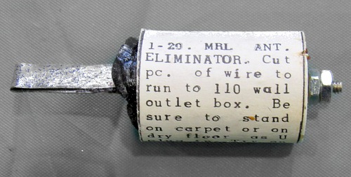
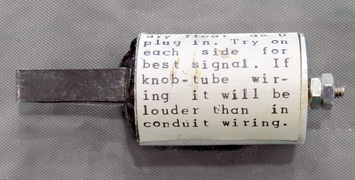
| The factory-made Antenna Eliminator was
once incorporated into a plug. It worked by plugging it into
an AC outlet, which allowed you to use the house wiring as
an antenna. The MRL version did away with the plug and
just used a single spade. This is found in section G of the
catalog, which listed antennas and accessories. By 1983 most
of the items on this page were reduced to blank spaces. By
1986 section G no longer existed, though the index still
referenced it. At that point, the antenna eliminator was
only found only in
the MRL Radio Flyer. |
| Photo by Doug Wilson |
|
| |
|
|
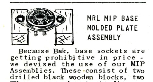
MRL PLATE MOUNTING ASSEMBLY |
|
|
| |
|
|
| Two wooden blocks and screws
(socket not included). 20 cents! |
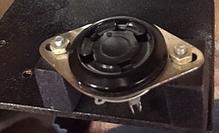
| "MIP" means "Molded In Plate." The
socket is molded into the mounting plate. |
|
| |
|
|
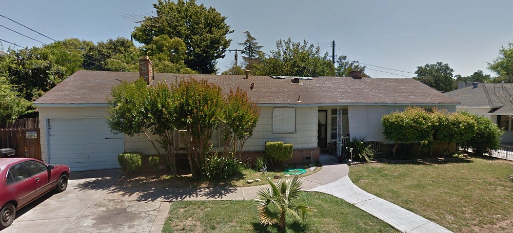
In 1970 Elmer and Mabel moved to
2612 Butano Drive, Sacramento, CA
Many of the Osterhoudt residences were one
story with a garage. MRL was in the garage. |
| |
|
| |
|
|
| |


