The Modern Radio
Laboratories
® One Tube All Wave Receiver
|
|
|
|
|
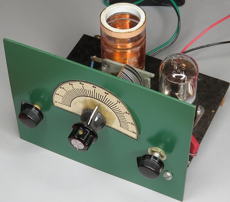
This is a
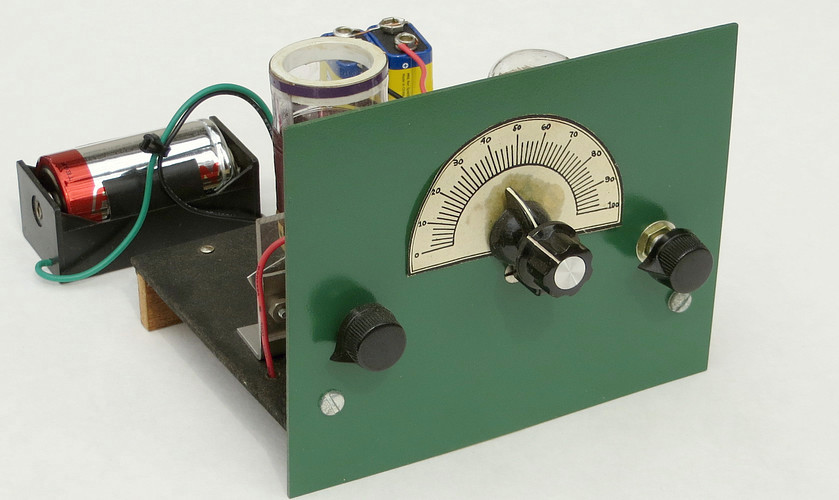
Modern Radio Labs 1 tube regen radio, purchased as a kit from Elmer
Osterhoudt in 1985. |
|
|
|
|
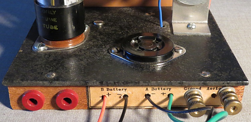
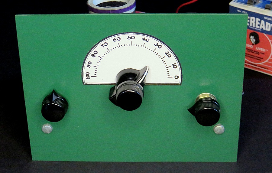
Headphones, antenna, ground and battery connections are
all are in the back. The front panel measures 4.5" x 5.5"
and is a copper-clad board, though the manual (printed in 1953) suggests
using a 4.5" x 6" aluminum panel. |
|
|
|
|
|
The tuning capacitor has a vernier mechanism that is built
into the capacitor shaft. This allows it to be mounted directly to the
panel.
Elmer added this at no extra charge. This type of vernier wasn't sold in
the MRL catalog. |
|
|
|
|
| |
|
|
|
|
| |
Phone jacks on the left, antenna
and ground on the right. |
|
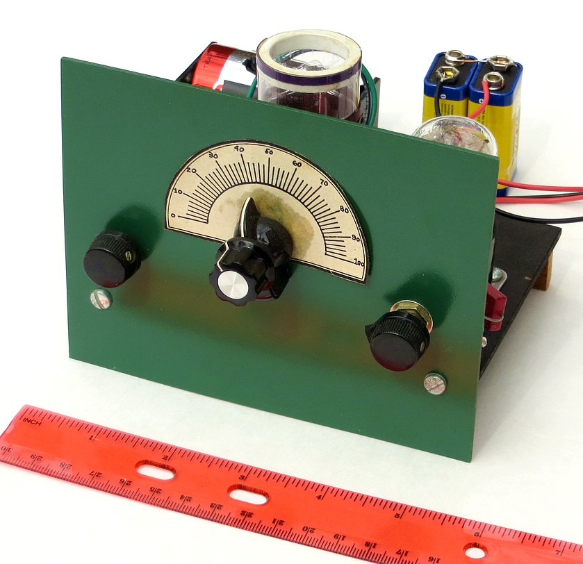
This model is in pristine condition. |
|
|
|
|
|
|
|
|
| |
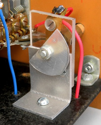
MRL hand-made antenna tune
capacitor. |
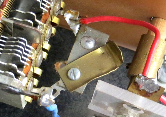
MRL-made switch on main tuning
capacitor. |
|
|
|
|
|
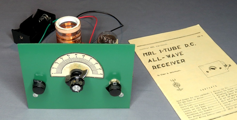
Radio and instruction manual to assemble it.
The copyright date on the instruction manual is 1953 but MRL had
been selling the plans since 1940. |
|
|
|
This radio was purchased in
1985 from the MRL catalog.
Click for full sized view. |
|
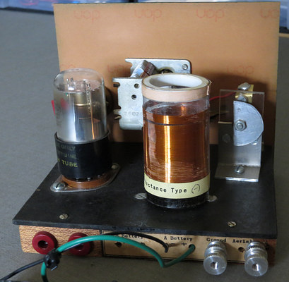
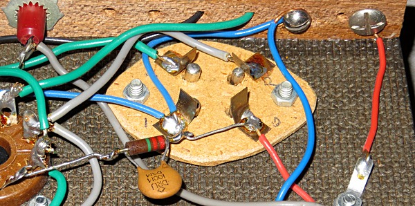
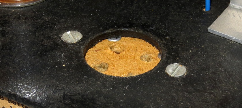
It's almost an accident that the radio remained in such
fine condition. It was because of the hand made coil socket, which came
already mounted on the base by Elmer. |
|
|
|
|
|
|
|
|
| When mounted beneath the base there is a 1/8" gap
between the coil and the socket. The coils kept popping out! To
listen to the set you had to hold the coil down with your finger. I
put the set in a cabinet, intending to modify it the next week.
That was 28 years ago. |
|
|
|
|
|
|
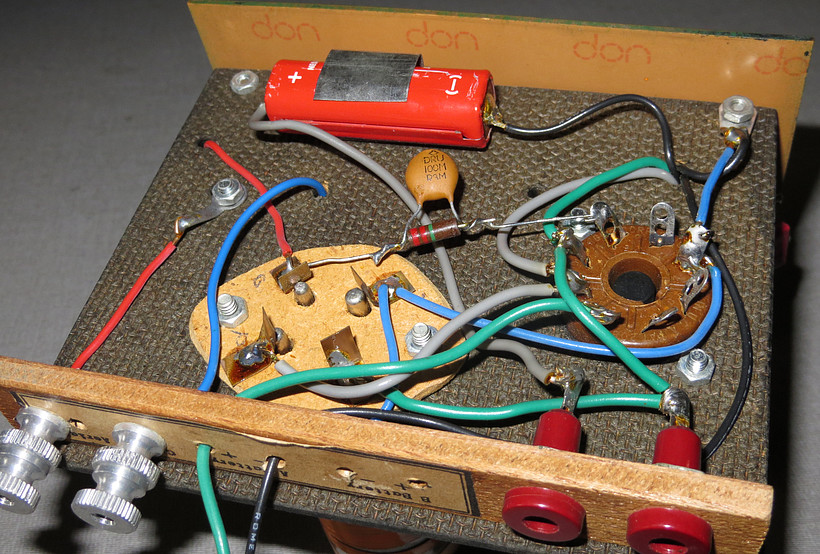
The battery is a 22.5 volt Eveready #505.
|
|
|
|
|
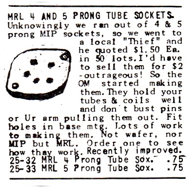
The reasoning behind the handmade coil socket, from "RADIO
FLYER No. 1, June, 1982."
|
|
|
|
|
|
|
In February of 2013 it was time to finish the
project. The coil socket and dead battery came out. In went a
Chinese made coil socket from ebay. Elmer rolled over in his grave! |
|
|
|
|
|
|
|
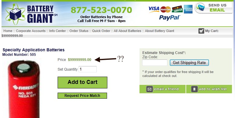
You can still purchase the battery, for around 100
million dollars! I dropped this into the shopping cart and the price
remained at $99999999.00. In reality they can be had for about 12 bucks,
but I tortured Elmer enough with the Chinese
coil socket. He recommended two or three 9 volt batteries in series. |
|
|
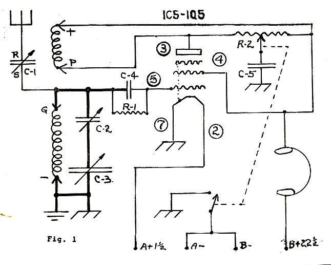
Drawing by Elmer Osterhoudt.
C1 = Two plate variable capacitor
C2 = 25 - 280 mmfd variable mica trimmer
C3 = 365 mmfd variable capacitor
C2 and C3 are set so the total
capacitance is 140 mmfd. See note below.
C4 = .0001 mfd mica capacitor (100 picofarad)
C5 = .00048 mfd mica capacitor (480 picofarad)
R1 = 2.2 megohms
R2 = 0 to 10K - 50K
NOTE:
Elmer's early 1 tube sets used a 140 mmfd variable capacitor.
When these became unavailable he used a 365 mmfd cap, with a 280
mica compression cap in series with it (C2 and C3). He set the
trimmer at his shop so that when installed, C2 and C3 would
equal 140 mmfd.
The photographs above show a later version, where C2 is no
longer used. Instead, Elmer found a supply of multi-section
variable capacitors. He added a switch to connect the rear
section if you wanted more capacitance for the broadcast band.
|
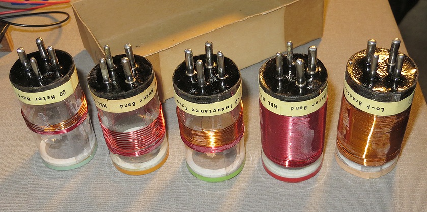
| COIL INFO - Coil
forms are 1.5" diameter |
| BAND |
PRIMARY TURNS |
GAUGE |
TICKLER TURNS |
GAUGE |
| 20 Meters |
4 |
22 |
5 |
26 |
| 40 Meters |
10 |
24 |
6 |
26 |
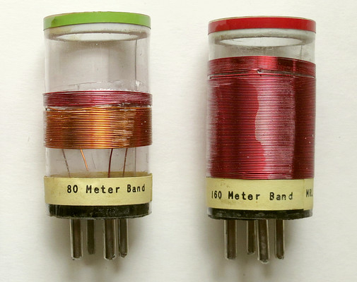
| 80 Meters |
22 |
24 |
6 |
26 |
| 160 Meters |
65 |
24 |
12 |
28 |
| HF BCB |
84 |
28 |
14 |
28 |
| Broadcast |
120 |
32 |
20 |
32 |
| LF BCB |
170 |
34 |
25 |
32 |
| |
|
|
|
|
|
|
|
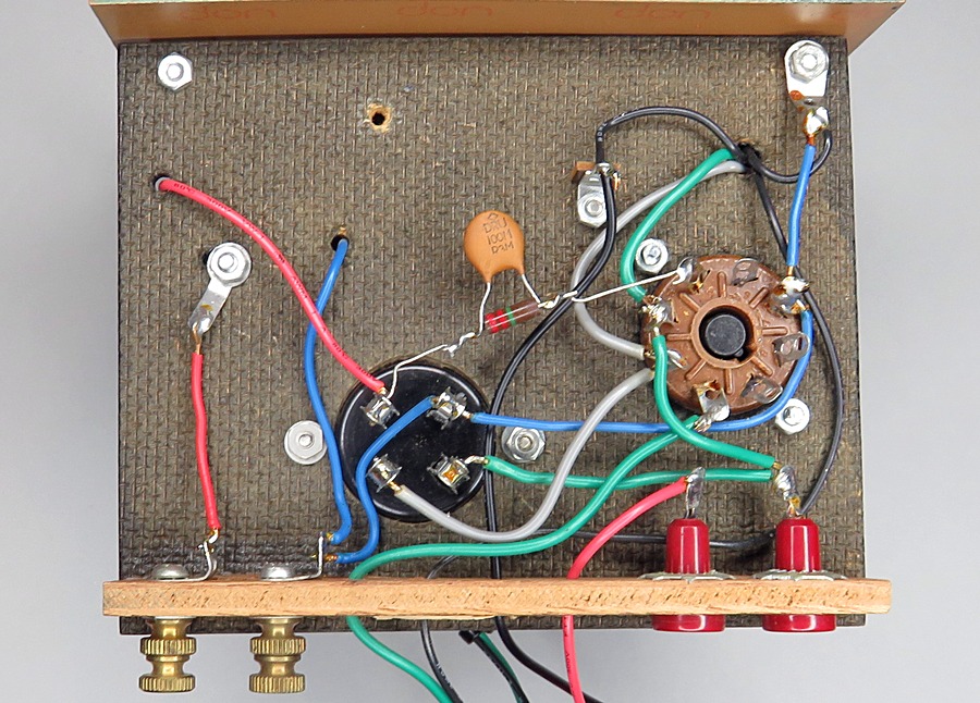
The rewired base. The battery is gone, the coil
socket has been replaced, and the binding posts are now brass. |
|
|
|
|
|
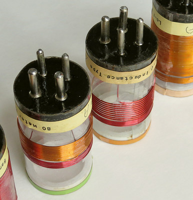
This is a set of MRL coils. Except for the pins and
the wire, they were completely hand-made by Mr. Osterhoudt. |
|
|
|
|
|
Crooked pins and sloppy coil cement. Today these coils are
treasures.
The ultimate MRL coil would have Elmer's fingerprint on it. |
|
|
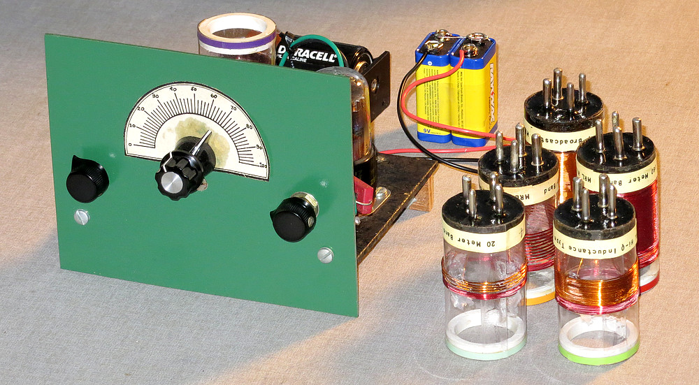
The complete setup, minus the high impedance headphones. |
|
|
|
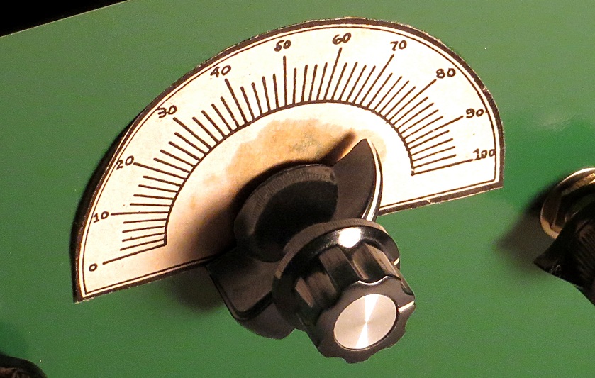
In 2023 the radio got a new dial scale. After 38
years the old one started looking ragged. There had always been a
mark on it that was made by the oil in the vernier mechanism of
the tuning capacitor. The old one had been printed, cut out, and
applied by Elmer Osterhoudt himself, so I pulled it off while
sobbing bitter tears. (That's "tears" that rhymes with
beers, not bears.)
As a concession, the label is a copy of the 1953 label that is printed in
the manual, but it had to be enlarged to match the size of the old
one. The 1985 knob was also replaced with a more appropriate
one. It may have looked cool in 1985, but today the market is
saturated with Chinese knock-offs and you see them everywhere.
Observing the knob with the silver insert, one would assume the
original knob had been replaced, when in fact, it wasn't.
Ironically, now it has been. |
|
|
|
So how well does it work? |
|
A 1.5 volt D cell powers the filament of the
vacuum tube. The set comes on instantly, there is no warm up time.
In pitch dark the tube gives off a faint orange glow.
With a long wire antenna and no ground it had no trouble
picking up stations on the broadcast band. My usual "test" of a
radio is to tune it to AM 1210, broadcasting from Philadelphia. It
is hard to pick up here in Upper Gwynedd, PA because their
transmitter is in Moorestown, New Jersey! I was able to find it
after some searching on the dial. Various short wave stations came
in with no trouble at all.
However, without being grounded the set suffers
from hand capacitance on weak stations. There is also a problem with
capacitance in the headphone cord. If I took the headphones off and
put them back on a few minutes later I had to retune the set.
However, with an earth ground connected the set is more sensitive
and the hand capacitance isn't such an issue.
I was very
pleasantly surprised at how well this little set works. I tried
various numbers of 9 volt batteries. The set worked with 9 volts to
45 volts. (It BARELY works at 9 volts and I could have gone higher
than 45 volts but Elmer showed 22.5 volts in the schematic.) I
settled on 18 volts.
The headphones used were a pair of Superex Deluxe SD, made in USA,
with an impedance of 2000 ohms.
I kept Elmer's coil socket, it's a piece of radio history.
|
| A MYSTERY |
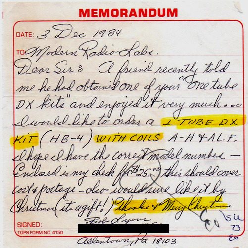
After looking through my records I found
that the set I got in the mail was intended for Robert W.
Lyons of 24th Street in Allentown, PA. We both ordered the
same thing.
Here is the strange part: I have the envelope addressed to
Robert Lyons with a return address of Modern Radio Labs. In
the envelope is the order (from Robert Lyons) for the one
tube set, dated December 3, 1984. Also included is the
letter Elmer wrote back to Robert explaining that he mounted
the vernier dial to the front panel. The stamps are
cancelled. The cancel date is March 1985. If the stamps are
cancelled, it must have made it to the Lyons residence! So
how did the envelope sent from MRL to Robert Lyons end up
being sent to me?
Robert ordered the set as a Christmas
present. My theory is that three months after Christmas he
received the set in the mail, then sent it back to MRL along
with the envelope. Elmer got my order in March and sent me
the set Lyons sent back to him, with the envelope and order
form from Lyons still in the box. The set came with the
vernier dial already mounted on the front panel, as stated
in the letter to Robert.
Anyone who has ever ordered from the old
MRL knows how long it took Elmer to send out the order. The
fact that he had to include a personal note with each order
didn't speed things up any. For Robert Lyons to send in an
order in December of '84 and not receive it till March of
'85 was perfectly normal for MRL.
In January of 2016 I found a phone number for
Robert and called it. His wife answered and verified I had
the correct name, address and phone number. When I mentioned
"radio" she said, "I got rid of all those radios last year.
My husband has been passed away for 30 years." I apologized
and hung up. He died in September of 1985 at the age of 51.
|
|
|
|
|
A brief video is below. |
|
|
|
|
|
Want to build your own set? The complete handbook written
by Elmer Osterhoudt can be found
here. |
|
|
|
|
|
|
|