The Ferrite Ferret
Construction Notes
 

       Analog Dial         Ferrite Ferret   Construction #1   Construction #2   Notes   Ron Buckwell

Ferrite Ferret
DONE! (for now)

Naming the radio.
 
Andrea
It was Andrea who named the radio "The Ferrite Ferret" in a shameless act of near plagiarism, just about stealing the name "Ferrite Fox" outright.

Some notes on the LM386 circuit.
 
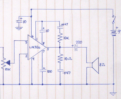
As noted before, a bypass capacitor is needed from pin 6 to ground. This can be any value from .01 to 220.

Pins 2 and 3 are interchangeable. However, the spec sheet shows pin 2 with a minus sign and pin 3 with a plus sign,
so pin 2 was grounded in this case.

The 10 MFD capacitor between pins 1 and 8 boosts the gain. You can try leaving it out initially, then add it if you need more volume.

The .0047 cap and 10K resistor from pin 1 to pin 5 is a tone control and removes hiss. They can be omitted.

The 100 MFD cap on pin 7 is supposed to "stabilize" the amplifier. It can be omitted. Pin 7 can be left open or tied directly to ground.

The 220 MFD cap from pin 5 going to the speaker is necessary, but the value isn't critical. Changing it will alter the sound.

The 10 Ohm resistor and .047 mfd capacitor from pin 5 to ground is called a Zobel network. This is used to make the impedance of the loud speaker appear as a steady resistance to the LM386, and prevents it from going into self oscillation.

The Ferrite Ferret works very well with the parts shown in the schematic. The LM386 design is over 30 years old and has been used in millions of commercially made radios.  I haven't turned the volume all the way up on the set because I'm afraid of damaging the speaker. It's LOUD!


Some notes on the "power supply"
What are these diodes used for?
 
The TA7642 runs on 1.2 to 1.6 volts. The MK484 needs 1.1 to 1.8 volts. The radio is powered by a 9 volt battery.

The Experimental Radio Project (seen elsewhere on this site) used a voltage divider and a variable resistor to control the voltage going to the radio chip. It's a great way to control the chip, if I do say so myself. These diodes seem to "sink" the voltage automatically so you don't need an extra control on the front. I've had my 9 volt battery down to 6 volts and the radio continued to work perfectly.

Using the resistor values shown, the chip is getting just about 1.1 volts. Change the values if you want to run hotter, or just add another diode. You can also run the chip on its own 1.5 volt AA battery, then you won't need a "power supply".


Any switching diode will work. 1N914, for example.

Switching diodes are cheap. These were 99¢ on ebay,
with free shipping. 30 diodes was the least amount I could purchase.

They are so small the soldering iron tip looks monstrous in comparison.


I wondered how the radio is working so well when using LESS voltage than the specs call for. A few days after the set was finished I found this excellent article which explains the characteristics of the AM chip under different voltages and configurations:
The RadioBoard Forums – The Best of the Best – Dan McGillis's MK484 Receiver Design


Notes on drilling Lauan plywood subflooring when used as a front panel.
Wood Chip
Drill slowly with a sharp bit. This stuff is soft, so don't use any force. The wood may split as the drill bit exits, so drill from the front.

Even while taking these precautions a small chip of wood shot out while I was drilling the hole for the pilot light.

At the exact same time, some guy started screaming something about his eye. I didn't allow this to distract me while I was drilling, though he was annoying me.

 
Next