The Ferrite Ferret
Construction
 

       Analog Dial         Ferrite Ferret   Construction #1   Construction #2   Notes   Ron Buckwell

 
Step 1: Make some time.

Some guys seem to be able to churn out project after project. One guy in a radio forum wrote that he couldn't sleep so he built a beautiful radio during the night, with pictures to prove it. Not me, I just don't have the time or the skill.

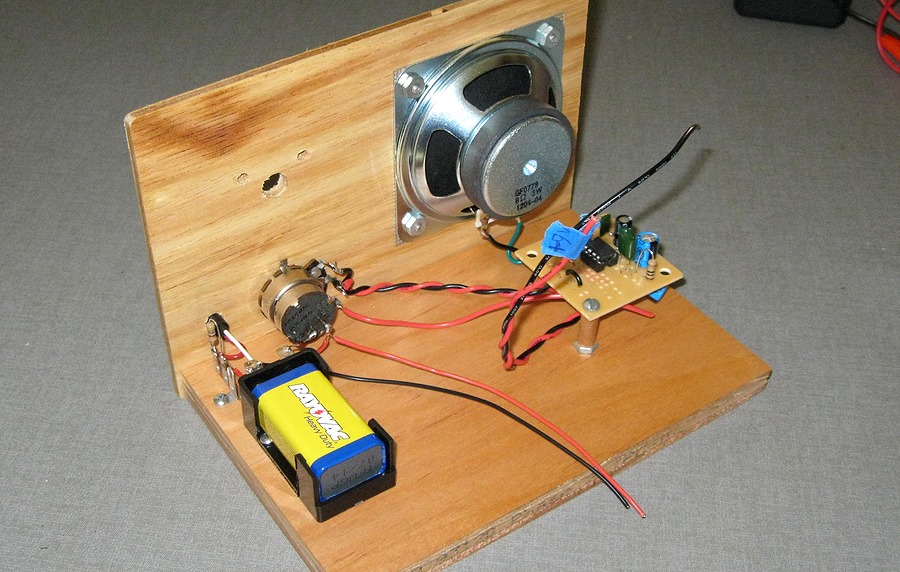
The Ferrite Ferret took over a month to build, an hour here and an hour there, usually late at night. There were parts and materials to acquire, schematics to compare and test, and the 
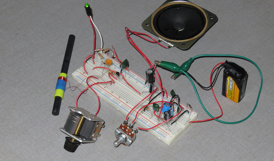
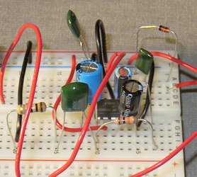
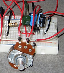
final version needed to be assembled. After the "Ferrite Fox" was built on the breadboard I spent two weeks experimenting to create the "Ferrite Ferret".

Several bottles of wine were consumed in the process. Actually, since it took a month, I'd say THIRTY bottles of wine were consumed. After midnight, of course. (I worked 4PM till midnight.)

You can't pull extra time out of a hat. To create more time I just stopped watching television.


Kirk on TV

Ferrite Ferret Schematic
Schematic of the Ferrite Ferret.
 It's very close to the one that comes with the data sheet for the TA7642.
 
Ferrite Ferret
Sloppy, but this is the completed circuit. Building this and experimenting with it was the really fun part.

The next step was to make the base and front panel.
 
Panels
Chassis
Front Panel
The front panel is a 1/8" piece of Lauan sub-flooring.

I was too lazy to find a square, so I used a greeting card and traced around it. Two sides were slanted by 1/16 of an inch.
I could hear Moe Howard saying "You know better than that!" (click on speaker)

I got the square and fixed the panel. The top corners of the radio are slightly rounded. What a thoughtful detail. The reality is that on the way down to the basement to cut out the speaker hole I dropped the panel down the steps. Instead of landing flat on its back, it bounced down the steps vertically like a wheel, rounding off one of the corners. I sanded the other one to match.


Building the audio amplifier
 
Then it was time to turn this..        .
LM386
into this...
...with this.
 
 
LM386
Alternatively, you can turn this...
LM386
into this...


...with this.


Search ebay for "LM386 module".


LM386 amp
IMPORTANT! You must connect a bypass capacitor directly from pin 6 (B+) of the LM386 to ground. You can't just connect it from B+ to ground anywhere you please. Solder it to pin 6!

Failure to do so will result in your amp going "BRRAAAAAAAAAKKK!!!" very loudly when you test it.
Snickering from your girlfriend in the other room follows.

Not knowing about the connection of the bypass capacitor set me back a week! It had worked fine on the breadboard and I couldn't figure out what was wrong. I even took the whole thing apart and rebuilt it - with the same result.

After I found this out I looked at every schematic I could find for this amp. Sure enough the capacitor is there, but
nobody states you need to connect it to pin 6! It's just a cap in the circuit going from B+ to ground on the schematics.
 

Back view
Here's how it looked after the amplifier problem was resolved.

volume control
TIP: Wire the volume control like this.
 

Next