|
Lafayette KT-135 EXPLOR-AIR radio kit |
 |
|
|
|
|
|
|
Since the radio is working, let's
perform an experiment! |
|
|
|
The schematic in the manual shows the
regen control wired this way. |
The pictorial instruction sheet says to
wire it like this. |
|
|
|
|
|
| Which way works better? We
need to cut the lead to the resistor at the regen control,
then compare how the radio operates with it connected to the
right hand lug vs. the center lug. When I touched the
resistor it broke at the arrow! That actually made
things easier.
|
|
|
|
|
|
Now we have the black alligator clip
on the resistor, the green clip on the center terminal of
the regen control and the white clip on the right hand
terminal. I had fantasies of flipping the switch and
observing a fantastic increase in performance. In reality,
all that happened was that the regeneration control needed a
tiny adjustment as you switched back and forth.
NOTE: The schematic in the
manual is incorrect. There is no connection on one side of
the regen control.
|
|
|
|
|
|
|
Experiment over. Let's take this thing
apart! |
|
|
| Right from the start there were
problems. I couldn't get the frickin' knobs off! Two of them
had broken set screws. One of them (the one pictured still
attached) didn't seem to have a set screw with a head on it,
so I started to drill it out. Andrea came to take a look.
There was NO set screw. The knob was GLUED on. What a mean
trick! I had been drilling into the shaft of the volume
control. That dirty bum! (As Ralph Kramden would
say.) |
|
|
|
|
|
|
|
|
|
|
|
The greenish coating on the chassis
is oxidized cadmium. I was advised not to sand it or breathe
the dust, so I used Duro "TUB N' SINK JELLY" which is
normally used to remove calcium and rust. I then polished it
five times with Brasso. I wanted it to remain dull, but it
kept getting shinier and shinier. The more I polished it,
the shinier it got. There must be a connection, but it
escapes me entirely.
|
|
|
|
|
|
|
|
| The collected parts. The fixed
capacitors will be replaced with silver-mica types for
improved stability, except for the .01 bypass caps which are
"Orange Drops." The "Chatter Teeth" (top left) are not part
of the project. |
|
|
|
|
|
|
This is what you got when you opened the box 50
years ago. I stole this picture from
|
virhistory.com. |
|
|
|
|
|
Using the photo on the left I've
identified the tubes in this particular kit as "IEC" by the
boxes. The tube boxes were magically restored in the picture
on the right.
|
|
|
|
|
|
|
|
| The original capacitor was restuffed
and sealed with beeswax at each end (I didn't have any red
wire). The set was also going to get a polarized plug since
there was a 50/50 chance the chassis would be "hot" every
time you plugged it in. |
|
|
|
|
|
|
|
Main parts are mounted. Notice the red
antenna connector. |
|
|
|
|
| The antenna connector, which was
black, was replaced with a red one. Someone pointed out that
neither color should be used for an antenna and convinced me
to get a yellow one. This style is getting hard to find. |
|
|
|
|
|
| How it looks in the manual vs. how
it looks in real life. Pictorial No. 2 makes you think it
will be easy to wire the set. Then you get to Pictorial No.
5 and things aren't so easy anymore. (A copy of the manual
is on the bottom of page five.) |
|
|
|
|
|
|
Small alligator clips were used as heat
sinks to prevent damage from the soldering iron. |
|
|
|
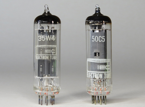
The vacuum tubes. |
|
|
|
|
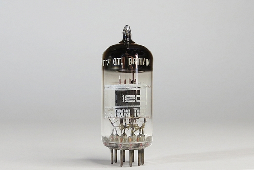
Inside your KT-135 you'll likely find an
IEC 35W4, an IEC 50C5, both made in Japan, and an IEC 12AT7
made in Great Britain. IEC, or International Electronic
Components, rebranded vacuum tubes at a factory in Long
Island, NY. You may also find Sylvania or Lafayette brand
tubes.
In 1965 Lafayette sold GE, RCA, Mullard and
Sylvania brand tubes. In 1966 the Sylvania brand was
replaced with Lafayette, so that can help narrow down the
date of the radio. The Lafayette 35W4 and 50C5 were
rebranded Sylvania tubes, but the 12AT7 was made by Mullard,
contrary to their "Made In USA" claim in the catalog.
Sometimes it's obvious the original tubes have been
replaced, especially if the radio was sold online. The tubes
were scavenged from the KT-135s in the 1960s and '70s to be
used in the family table radio, then replaced by a seller 50
years later. For example, Lafayette didn't supply tubes
labeled Sears Silvertone or Motorola with the KT-135 kit, so
these were pulled from another radio, as were tubes labeled
Admiral, Emerson, or Philco.
|
|
|
|
|
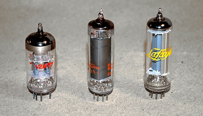
The 12AT7 in this neglected KT-135 has
been replaced with a Philco. |
In the 1966 Lafayette catalog, a Lafayette 35W4 was
$0.48 and a 50C5 went for $0.90. A 12AT7 was $1.29. They
didn't sell the IEC brand tubes, even though you got three
with the KT-135.
IEC went bankrupt in 1980, long after the KT-135 kit was
out of production.
|
|
|
|
|
|
|
| When this radio was being restored I
was unable to acquire IEC brand tubes. Three "New Old Stock"
vacuum tubes were purchased, and one of them was a Lafayette
just by chance. I got them at
vivatubes.com. |
| |
|
|
|
|
|
|
|
|
Above is one of the
tubes after it was removed from its socket. Part of the
socket is still attached to the tube. Obviously the radio
isn't going to work again when the tube is put back. The
Lafayette tubes had a 2-year guarantee (the IEC had none)
but they supplied low quality phenolic plastic tube bases
with the KT-135, which sold in the catalog for 18 cents.
It's doubtful anybody ever did this, but you could go into
the Lafayette store and upgrade to a Bakelite socket for 31
cents. Whaaaat??! 31 cents?! That's almost double the price,
those thieves!!! |
|
|
|
|
|
|
|
|
|
|
|