Modern Radio Laboratories
® /Alfred P. Morgan Mash-up
|
|
|
|
|
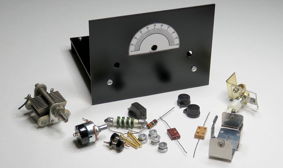
More parts. A "D" cell battery holder is lower right. I
don't know how old it is, but it was made in New York. |
|
Why go through all the trouble of making
another MRL 1 Tube radio?
What got me started was an email from a person named Keith
Ford.
On November 3, 2018, Keith emailed me with questions
about the MRL 1 Tube Receiver. He said he wanted to clone
one, down to Elmer's home made coils and coil sockets. He
asked for close-up photographs of the MRL coil socket, top and bottom. I had
an extra (original, priceless) HB-4 handbook and mailed it to him. Ironically,
while it was en route to his house the entire MRL collection
of literature was put online.
Why would I mail an original MRL handbook to Keith? Because
anyone who would want to copy an MRL coil socket deserves a
handbook printed by Elmer Osterhoudt himself!
I liked the idea of building another one of these sets so
much I decided to make one myself. |
|
|
|
|
|
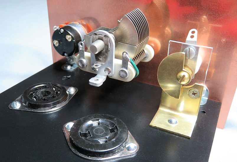
Parts mounted on the front panel
and base. Because Sloan Freeman made me paranoid about the
"conducting paint," the bottom of the antenna tune cap is
covered with a piece of tape. The screw goes through an
over-sized hole and a mica washer prevents the nut from
contacting the bottom of the base. |
|
|
|
|
|
|
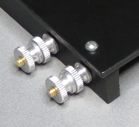
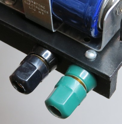
I also swapped my cool homemade binding posts with
ones that don't conduct to the chassis. |
|
|
|
|
|
|
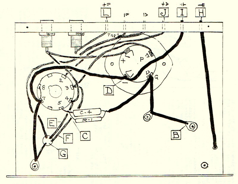
The radio will be wired according to this easy to
follow diagra- ...What the dickens? |
|
|
|
|
|
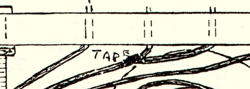
Does that say TAPE?? C'mon man.
FUNK DAT! |
|
|
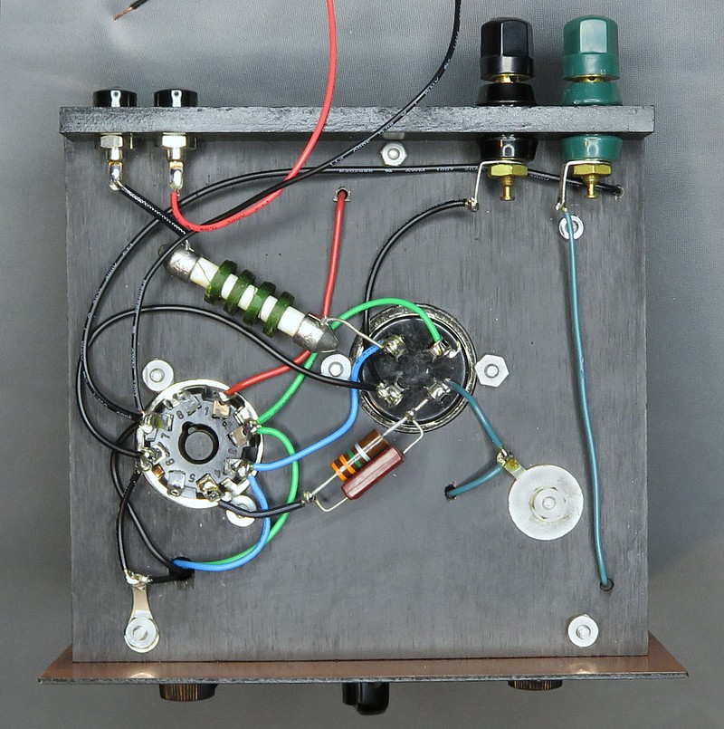
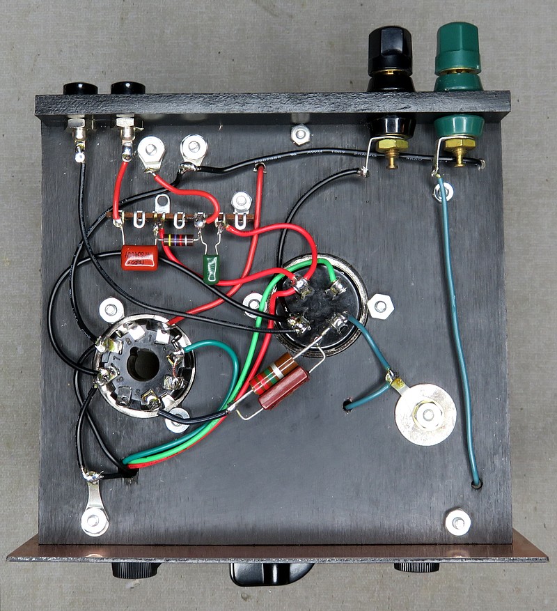
Here it is wired, with the choke in place. No tape;
pin 8 on the tube socket is used as a tie point.
The explanation of the tape and pin 8 is on page 12-A in the
handbook. |
|
|
|
|
|
|
|
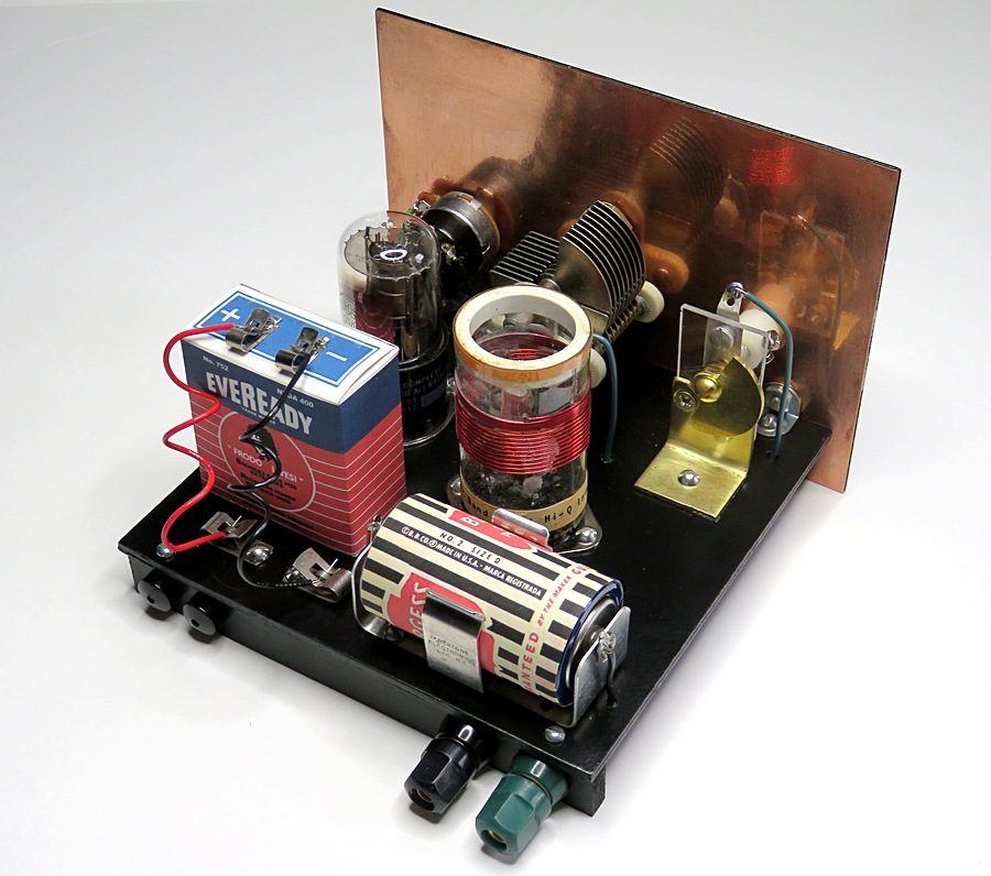
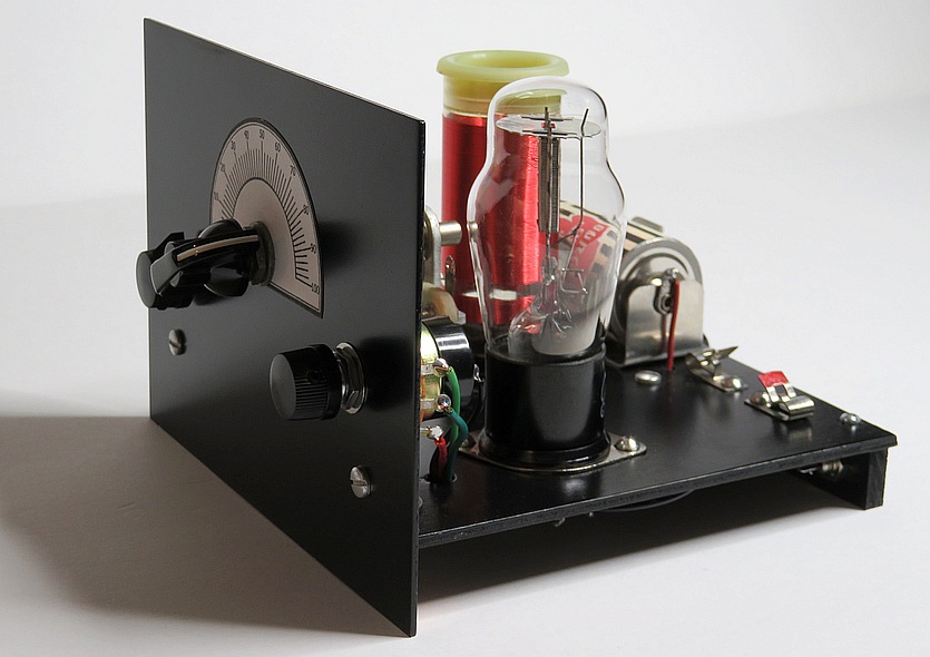
The completed MRL One Tube clone. |
|
|
|
|
PROBLEMS! |
|
|
After firing up the set it was found the
regeneration was very hard to control. It would instantly go from no
feedback to too much feedback. There was no "sweet spot" on the
control knob. This made the set pretty much unusable.
A guy named Sloane Freeman wrote to me and said I should have used
Elmer's exact plan, which didn't have an RF choke. I jumpered the RF
choke but it didn't make much difference. Then Freeman figured it
out from 1,300 miles away. The regen pot had an audio taper. It
should have had a linear taper.
|
|
|
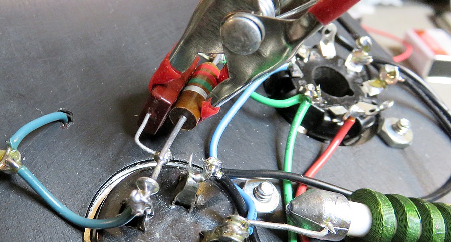
Changing the grid leak resistor from 3.3 megohms
to 2.2 megohms. It's held with a clamp, waiting for solder. |
|
|
|
|
|
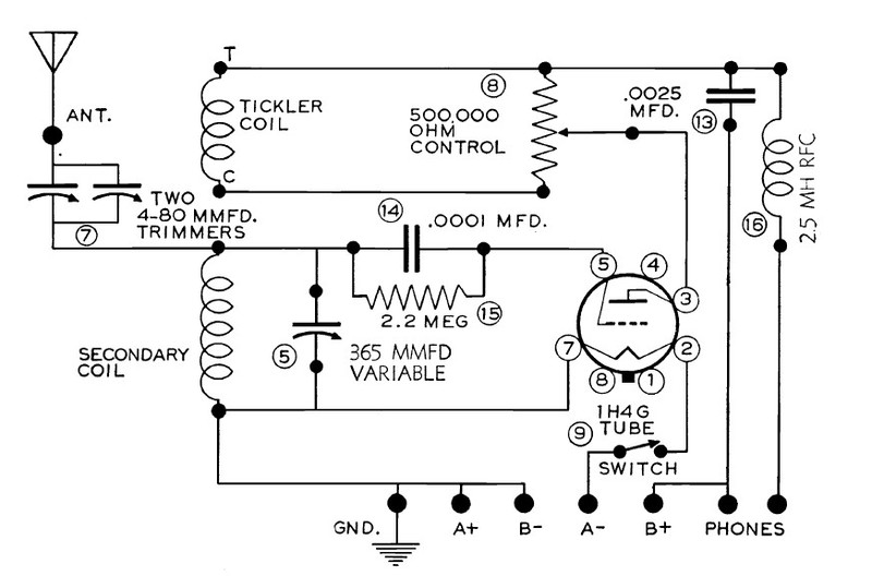
| There is more than one way to produce
feedback. This is how Alfred P. Morgan did it in 1954. All that is
needed to turn the MRL set into a Morgan set is to connect the wiper
of the 500K control to the plate of the tube. (It was also necessary
to tie pins 3 and 4 together on the 1C5 tube. Morgan used a 1H4
triode.) |
|
|
|
|
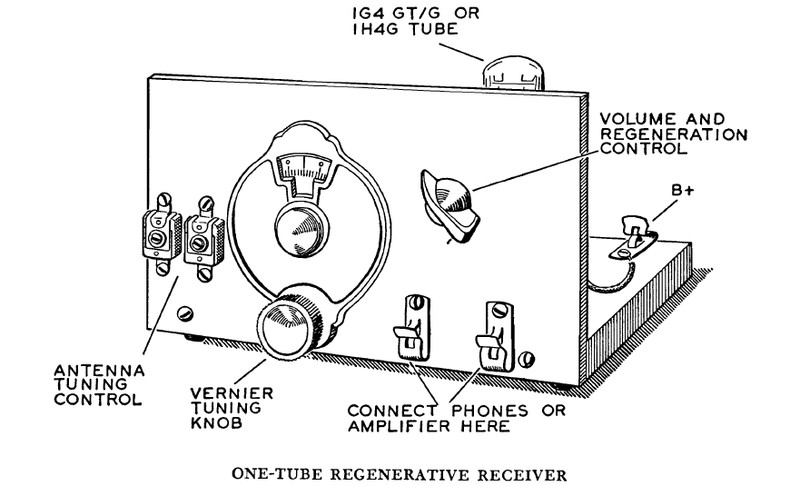
| I've always wanted to build one of these. For
some reason I thought this radio was larger. It's the exact same
height as the MRL 1 Tube! By moving
a few parts around, the MRL set was made into a Morgan set. This is
from
The Boys First Book of Radio and Electronics. |
|
|
|
|
|
Rewired per the Morgan schematic. The green
capacitor is part No. 13 on the Morgan schematic. The resistor and
the brown capacitor are from page 12-B in the MRL handbook.
Basically, the resistor is wired in place of the headphones and the
audio is picked up between the brown capacitor and ground. Now the
B+ doesn't go through the headphones, the choke isn't needed and the
set can be connected to an amplifier.
Mike Peebles also uses this setup in his tube radio kits. |
|
|
|
|
|
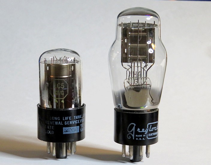
1C5 tube vs. 1H4 tube |
Before we test the radio, let's look at the two different
vacuum tubes.
MRL used a 1C5. Alfred Morgan used a 1H4. What are the differences? |
|
|
|
| |
|
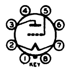
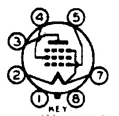
The 1H4 is a Triode. Filament voltage is 2
volts @ .06 amp
Pin 3 is the plate, pin 5 is the control grid. |
|
|
|
| |
|
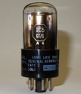
The 1C5 is a Pentode. Filament voltage is
1.4 volts @ .1 amp
Pin 3 is the plate, pin 4 is the screen grid, pin 5 is the control
grid. |
|
|
|
A Triode is the simplest form of vacuum tube,
invented in 1906 by Lee de Forest. To
use the 1C5 Pentode as a Triode, we just connect pins 3 and 4
together on the socket. Now both tubes can be used in the Alfred P.
Morgan circuit.
Observe the filament voltages for the tubes. Using a flashlight
battery will overdrive the 1C5 filament by .1 volts, and it burns a
tenth of an amp, so it gets hot! The radio will easily work with 27
volts (three 9 volt batteries) on the plate.
The 1H4 filament is rated at 2 volts, so the flashlight battery
isn't quite up to snuff. It also runs at a cool .06 of an amp. The
filament battery will last quite a bit longer with the 1H4, but 27
volts on the plate isn't going to cut it. There aren't enough
electrons coming off the filament because it isn't hot enough. We
need the 45 volts on the plate that Morgan said to use.
Both tubes can handle 90 volts or more on the plate. Here are the full
specs for the tubes: 1H4
1C5 |
|
|
|
|
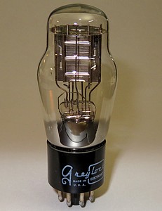
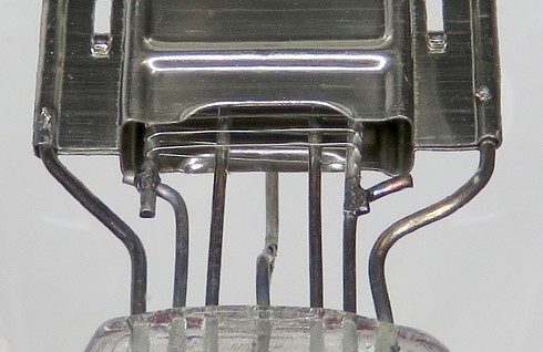
Vacuum tubes have almost magical properties,
considering they're just strategically assembled bits of metal. This is
the 1H4. On the left you can see the grid going up inside the plate.
On the right is the getter. The tube has a very small getter mirror
on the glass, which shows it was made with a very hard vacuum.
The tube is branded "Greylock." According to a thread on the Antique
Radio Forum, "Greylock was one of the shady operators in the tube
rebranding industry. They would take surplus stock, military
surplus, manufacturers overstock, and seconds, wash off the brand
markings, and stamp the tubes afresh, and then market these
(oftentimes used or out of spec) tubes as new, under their own name,
at a discount price."
The tube was acquired from a tube seller who had tested it and
compared the results with a New Old Stock tube. (A tube tester
pushes the tube past what it would encounter in a radio.) After some
research, I've found that this tube was probably made by RCA around
1952.
See one taken apart
here. |
|
|
|
|
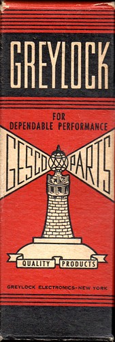
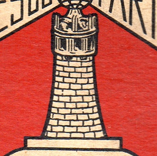
The Greylock tube box. It looks like somebody added the
bricks to the lighthouse by hand before printing it.
It's also labeled, GESCO PARTS QUALITY PRODUCTS." |
|
|
|
|
|
|
The radio with the 1H4 tube installed. |
|
|
|