The Experimental Radio Project
|
|
|
|
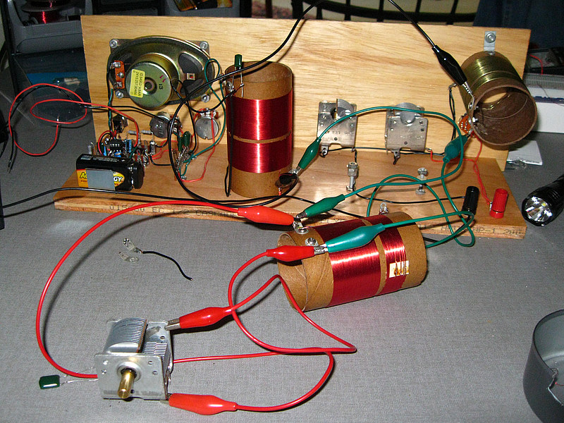
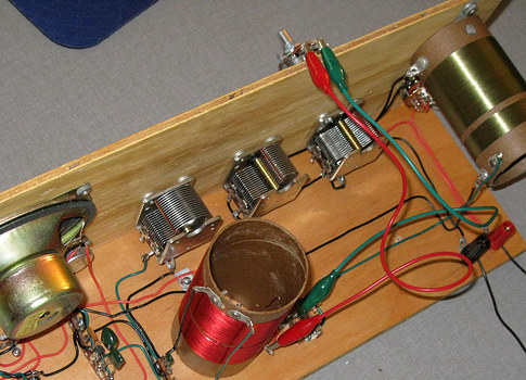
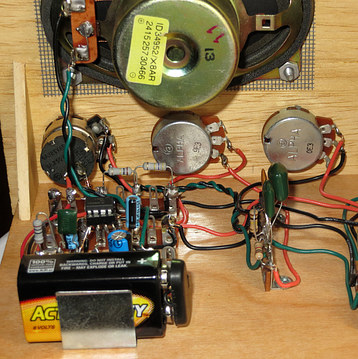
In this experiment, one of the Tandem Tuner coils is placed between
the antenna coil and the detector coil.
| It did not greatly improve operation of the receiver. What it needed
was another RF amplifier. The original RF amp broke into oscillation because
one or more of the parts were of the wrong value. All I could do
with my limited knowledge was to substitute parts. During one of
these experiments
I burned
the transistor out. I wish I could say, "There was a
bright orange flash followed by a loud report!", but in reality
nothing appeared different.
(though I burned my finger when I went to examined it.) |
|
|
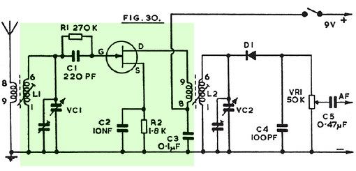
Then, while looking through "50 FET Projects" by F. G. Rayer I found
this
circuit.
Not only did it look like the exact circuit I was building, it had
the
values for the
RF amplifier components! |
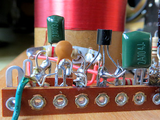
The RF Amp, Version 2. |
|
|
|
|
Now the radio worked very well. It was selective,
somewhat sensitive and had plenty
of volume. It
could pick up a few local stations with no antenna or ground.
Adding
a longwire antenna greatly increased its performance.
A ten
foot long piece of wire substitutes for an earth ground and
makes it super selective.
It also works with a loop antenna
connected to the antenna and ground connectors.
There was still one
small problem..... |
| |
|
|
|
|
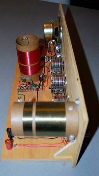
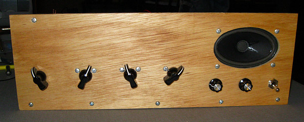
It was soon apparent that a really strong signal could
still overload
the detector.
The answer was to shunt some of the battery and
RF output to ground with a
variable resistor. In this picture it's
hanging over the top of the front panel. |
The new control would be known as "RF GAIN" when the front
was labeled.
This posed a problem as there wasn't any logical place to
put it. |
|
|
|
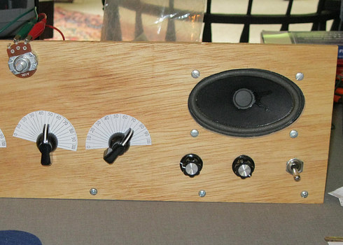
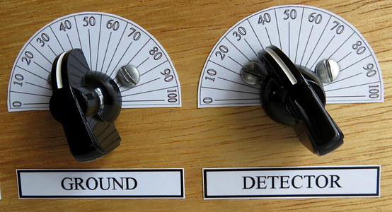
At Andrea's suggestion, the On/Off switch and volume control
were combined.
The Detector
gain control was then moved to the right, leaving an empty hole
for
the RF Gain control |
|
|
|
|
|
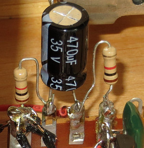
A few other experiments were tried. For instance,
this circuit stabilizes the power coming into the RF amp. |
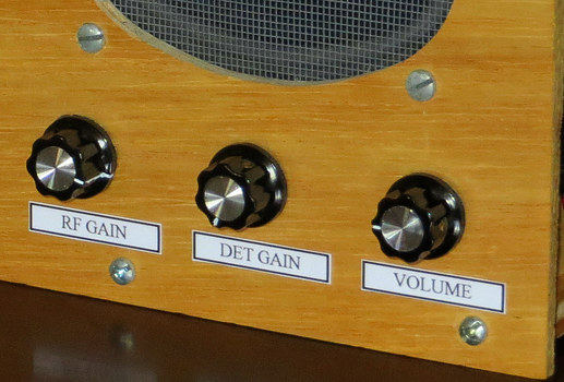
Finally, labels were were printed out on photo paper, sprayed
with clear plastic spray paint, and glued to the front
panel. |
|
|
|
|
|
|