The Experimental Radio Project
|
|
|
|
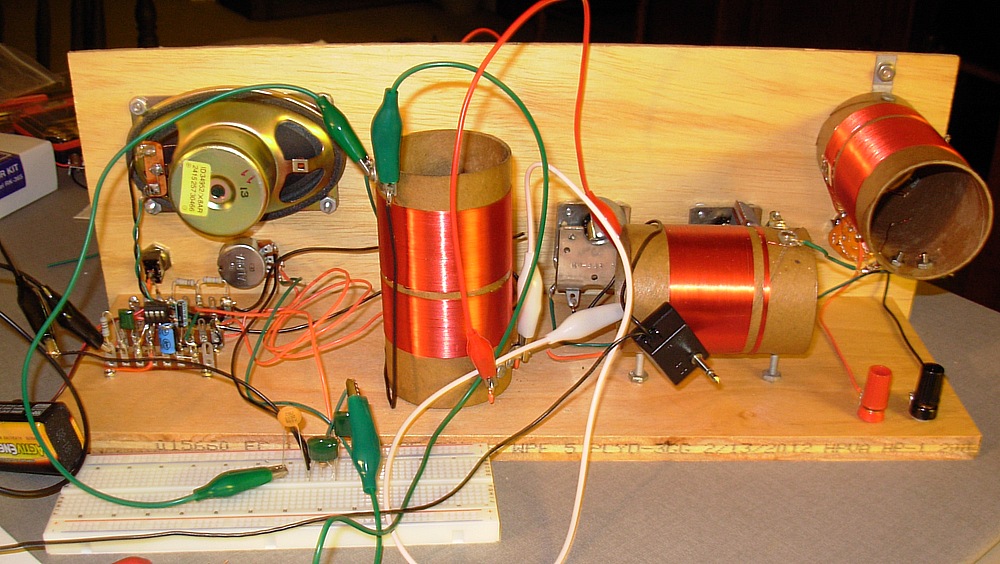
Now it was time to connect the 3rd coil to the RF amp and run a
crystal diode to the audio amp. Then I would be done!
I turned it on and
It howled like a banshee, with horrendous squealings and "motorboating"
as the dials were turned. The RF amp was oscillating.
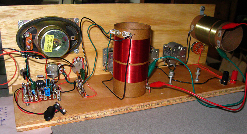
I began to substitute components, but because they were soldered in
they were being ruined every time I cut one out. Eventually I bought the
solderless breadboard seen at the lower left. This allows you to connect
components without soldering them. In this photo the RF amp is gone. |
|
A work-around to the RF amp problem:
|
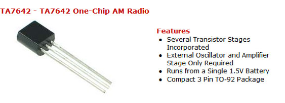
The TA7642 "radio on a chip" has an RF
amplifier built into it! Using this chip I could do away
with the external RF amp and the crystal diode. I really
wanted that diode in the circuit but it would have to go.
The only problem I saw was that the chip ran on 1.5 volts
but the radio used a 9 volt battery. |
|
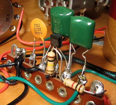
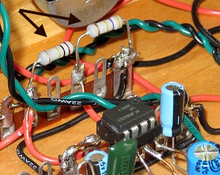
The completed detector circuit using the TA7642. I kept the
component leads long in case I had to take it apart. |
|
|
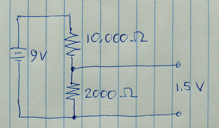
How do you get 1.5 volts from a 9 volt battery? With a
voltage divider. |
The voltage divider, which powers the TA7642 |
|
|
|
After all that I couldn't get the TANDEM TUNER to work, so it was
removed.
Surprisingly, with the coil, detector chip and audio amp I had a
perfectly functioning radio already. It didn't work very well
though.
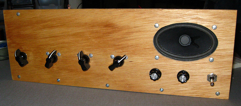
Notice another control has been added under the speaker. The TA7642 is easily
overloaded by a strong signal. To make the chip behave you
reduce
the
voltage to the chip. (as opposed to reducing the input signal). A
potentiometer was added in series with the voltage divider that
would
reduce the voltage by .5 volts. It could be controlled from the
front panel. Later this knob would be labeled "Detector Gain" |
|
|
|
|
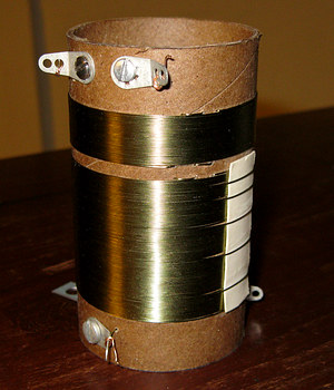
A new front end coil was made, using a design I knew worked
in crystal radios.
75 turns tapped primary, 30 turns secondary.
Radio waves would, of
course,
travel better through GREEN wire.
Sounds like common sense
to me! |
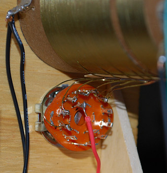
The coil was attached to the selector switch on the front
panel.
This meant the front panel had to come off, which meant
that everything attached to it had to be removed
first. |
|
|
|
|
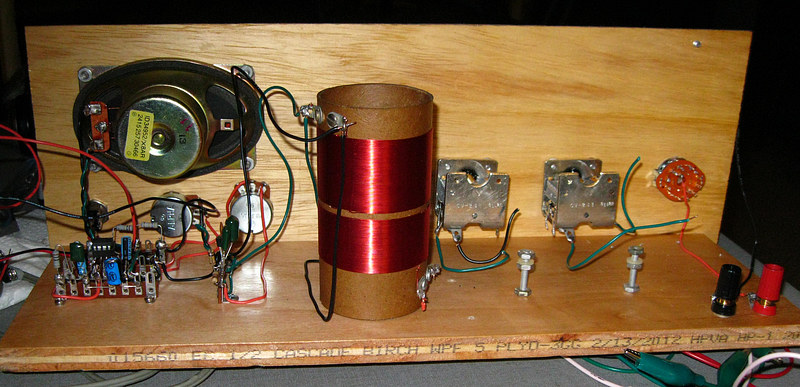
The new layout. All the controls on the front work, but the
radio itself still isn't working as well as I'd like. |
|
|
|
More work was needed. |
|
|
|
|
|