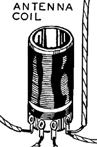
Remember paper drinking straws?
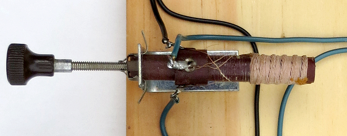
Why does it look like there are drinking straws coming out of the
bottom of the coil? Of course it's hookup wire, but my wire was covered in green rubber and didn't look
anything like that. What is that black stuff dripping down the coil? Is
the coil hollow or does it have a shiny top? Questions I asked myself as
a kid.
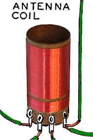
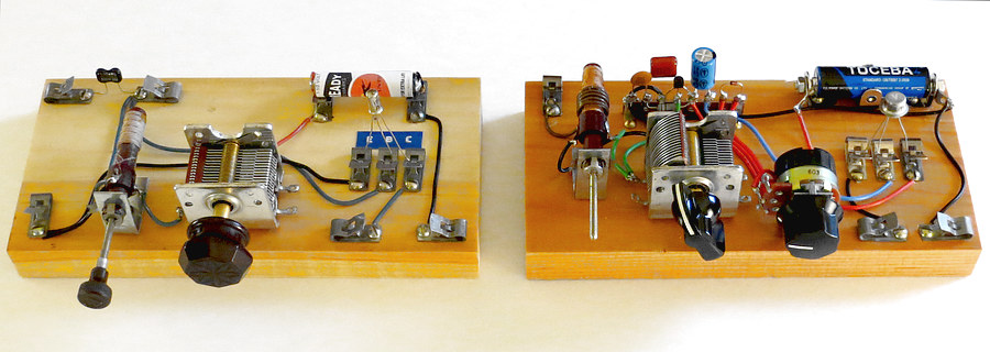
A clearer picture is on the right. This particular coil is
one and one eighth inches in diameter. The primary coil is 130 turns of #28 gauge
wire. The antenna - ground portion is 30 turns #28 gauge wire about 1/8"
from the primary. The original coil in the Morgan book was probably smaller, with smaller
gauge wire.
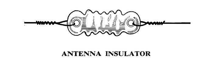
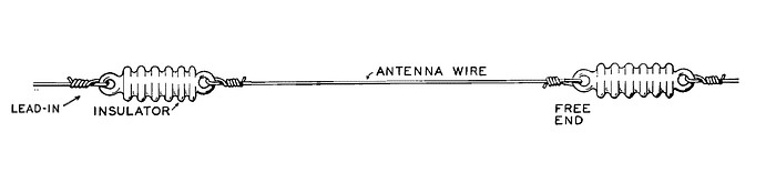
The Antenna
On page 50 of "The Boy's Second Book of Radio
and Electronics," Morgan shows us a "corrugated glass insulator
suitable for supporting a 50 to 75-foot receiving antenna." But what IS
it? In 1966 I looked and looked at this picture and couldn't figure it
out.
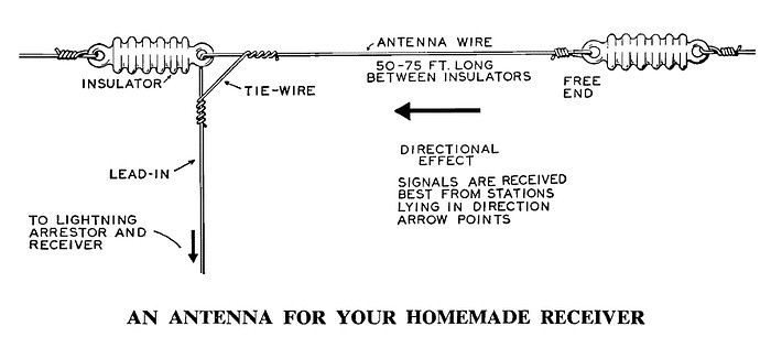
This is how they are used. They look important!
Well, you need those things on the antenna wire
if you want the radio to work, right? I didn't know what they were but I
looked around the house till I found something with a hole in each end.
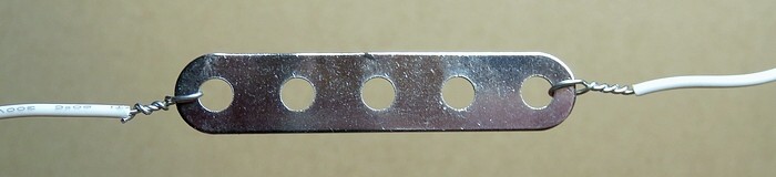
Then I hooked it up as above. You can see that the way I connected the insulator has
rendered the antenna wire completely USELESS.
This is what I used: an ERECTOR SET part. It had
a hole in each end and it was flat, just like the picture in the book!
In my ignorance I had used a conductor as an insulator, but I had also
stripped the insulation from the wires to match the pictures in the
book. I had broken and then reconnected the antenna and was completely
oblivious to it.
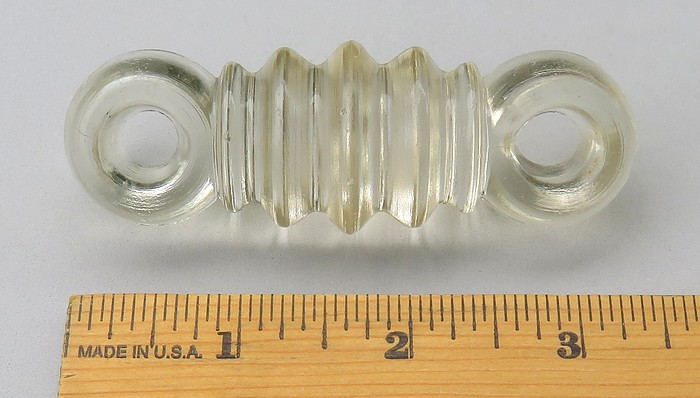
This is one version of what a "corrugated glass
insulator" actually looks like. This one is 3.5 inches long and an inch in
diameter. Thankfully, I didn't have one of these as a kid or I would have
broken my antenna with it. The next year I realized that I had merely
made a lousy connection with the Erector Set part and removed it,
splicing the wire back together.
By the way, there is a reason the insulator is corrugated.
Though the holes are physically TWO inches apart, an electrical current
traveling across the surface would have to travel FOUR inches. In a case
where the insulator becomes wet or dirty (or both) this increases its
resistance.
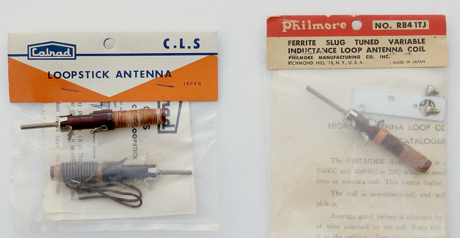
Ferrite (loopstick) Coils
Miller 6300
Miller 2002
Fat chance finding the exact
coils to make the two Morgan sets. Above are the Miller 6300 and 2002
coils from 1966. However, there IS a source for New Old Stock
equivalents. They can be purchased from
Peebles
Originals.
I wrote to Mike Peebles and he agreed to
be listed as a source of these coils, but they are not in his
online catalog so you have to ask him for them via email or phone call.
Expect to pay TEN TIMES what they cost in the 1960s, and it's still a
deal.
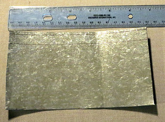
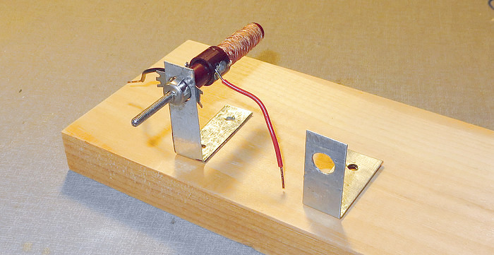
Coil Brackets
The Calrad brand coil doesn't come with a
bracket. This is how I made a couple:
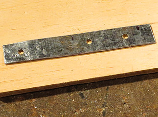
This is a scrap piece of
roof flashing. It can be cut with heavy scissors. I cut a 1/2" strip,
placed a piece of double-stick tape on half the strip, then folded it
over. The fold was flattened with a hammer. A 1/8" hole was
drilled near the fold, and two
more holes were drilled for the mounting screws.
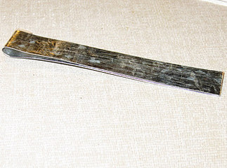
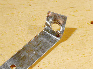
I tried to go up
in drill bit size in the left photo, but the
bit grabbed the metal. So instead of a drill bit, I placed a
round tapered file in the drill chuck and reamed out the hole. The bracket
was bent
90° and the excess was cut off the bottom.
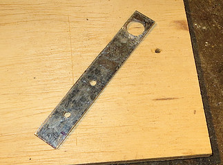
Two home made brackets. They don't look too bad.
They'll both be used further down the page.
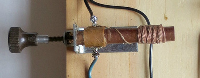
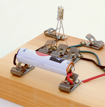
Battery Holders
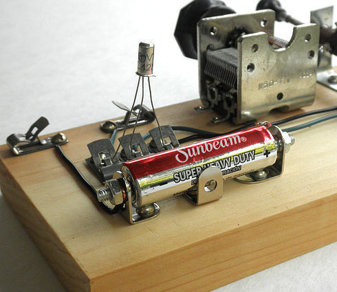
This was how I made a
"battery holder" in 1966. It was a quick way to mount a battery
using Fahnestock clips. The
battery is dedicated to the radio and when you have to replace it, the
soldering gun needs to come out. Back on page 3 you may have noticed
Morgan also soldered wires to his battery.
This battery holder was made with "Erector Set" type parts that
were purchased at the dollar store. It works well, the battery
"snaps" in. By the way, you can make the radio a lot
louder by using two batteries in series to make 3 volts.
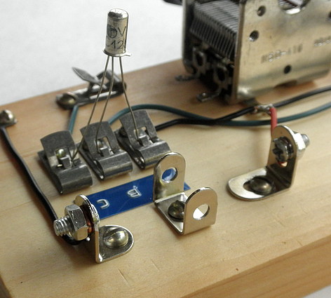
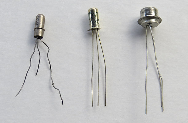
Germanium Transistors
Germanium transistors are
still cheap and easy to get on ebay (as of 2015). On the left is my
original transistor from Ree Electronics, purchased in 1966. Next to
it is a NOS TUNGSRAM AC125 from Bulgaria. Next is a CK722 / 2N107
generic equivalent. On the right is a transistor from Radio Shack,
still in the package. It's so old I don't want to open it, so I just
look at it.
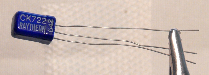
I almost bought this NOS CK722 but the price
went up too high ($27). There is no guarantee it would work
after all these years.
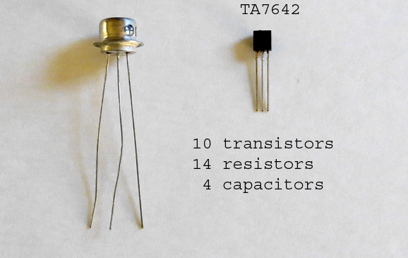
Improving the set
while keeping it "Morgan Style."
To improve one of the
Morgan sets we'll use a TA7642 AM Radio IC in place of the detector,
and keep the Germanium transistor
to use as an audio amplifier.
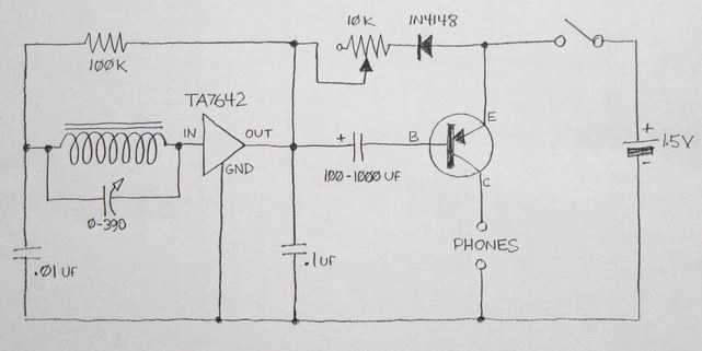
Here is the schematic.
Notice you still need the headphones to turn on the Germanium
transistor, just like in the Morgan set.
The 1N4148 diode and 10K pot are used to control the voltage to the
TA7642, which needs about .9 volts DC. When the control is adjusted
properly the radio will be loudest and most sensitive.
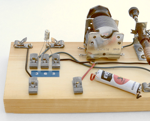
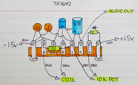
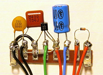
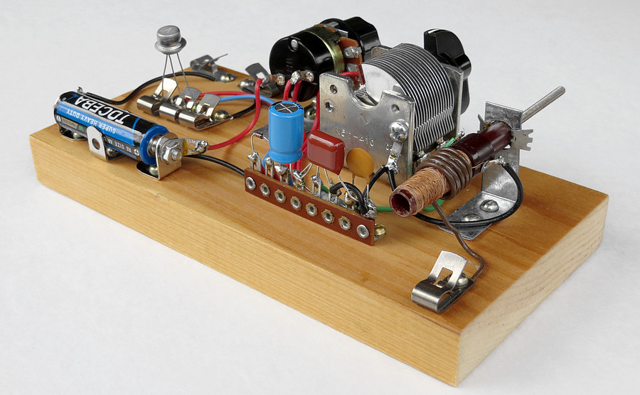
To keep the design
simple, the IC and its supporting components were put on a single
terminal strip. A picture was drawn first to get a clear idea of how
everything was to be wired. Then the terminal strip was screwed down
and the wires were connected.
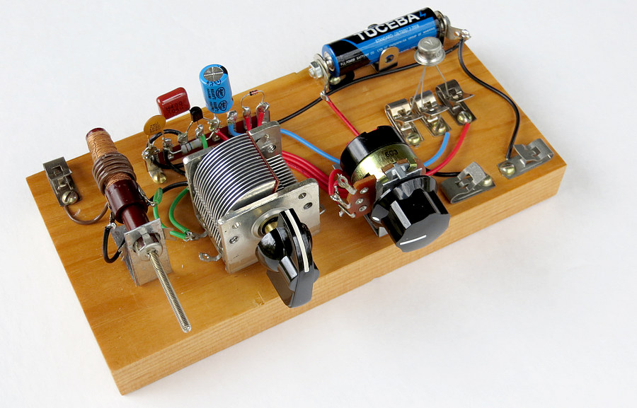
The "improved" Morgan set.
So how is this an
improvement? It doesn't need an external antenna or ground! It's
portable! You can now listen to the radio
in your automobile, take it to your campsite, and even use it while
in a canoe. (The bit about the canoe is a joke. Radio and science
magazines from the 1940s and '50s sometimes had articles about
"portable" radios you could build. They must have thought everyone
had a canoe or a boat, because that was a suggested place to bring
your portable radio.)
There is a Fahnestock clip
to attach an external antenna if you want to use one. The clip is
connected to a few turns of wire wrapped around the coil. The radio
can get very loud with an external antenna. Mine got so loud I was
worried about damage to my nearly-impossible-to-get headphones.
Did you notice the knock-off TOSHIBA battery? My grandson
Matt gave it to me. He said his mom bought 60 of them for
five dollars at Zerns, a farmers market in Gilbertsville, PA. Six
months later they had to go though the house finding every device
with AA batteries in them, because they were all leaking.