Further on in "The Boys' Third
Book of Radio and Electronics" is this receiver. It was off to Ree
Electronics for a coil and a transistor. They didn't have a CK722. The
CK722 was designed for hobbyists and Ree was an electronics retail and
repair outfit. You wouldn't find a CK722 in any piece of consumer
electronics. They sold me a Germanium equivalent.
By the way, the CK722 became the most popular
transistor in the world, but inside every one was a REJECT from the
hearing aid industry. In the early 1950s Raytheon was producing tens of
thousands of transistors a month, but only half of them met
specifications. If the rejects worked up to a certain point for gain and
noise, they were repackaged as a CK722.
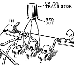
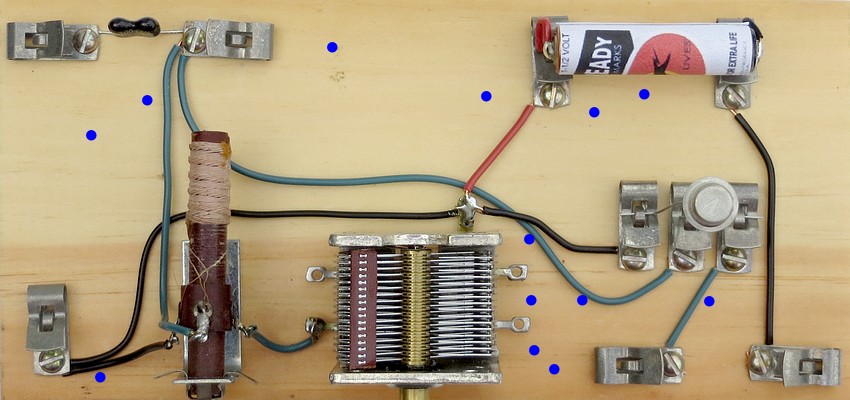
I didn't have a socket, so the
transistor would be mounted like this. I realized that by adding three
Fahnestock clips for the transistor, I wouldn't have to move any of the
others. The diode connections could become the battery connections.
Antenna, ground and phone connections could all remain the same.
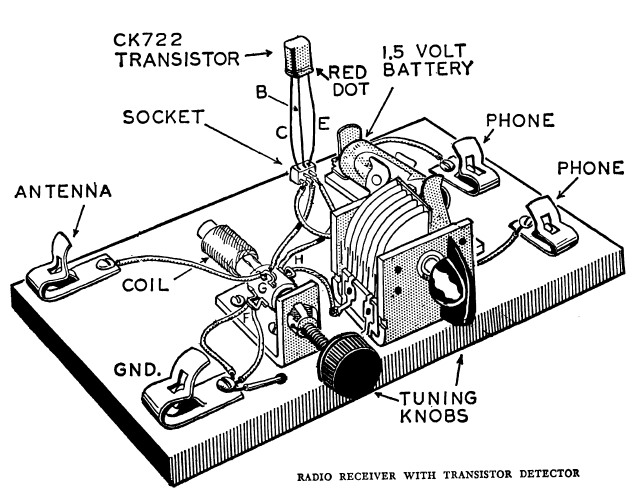
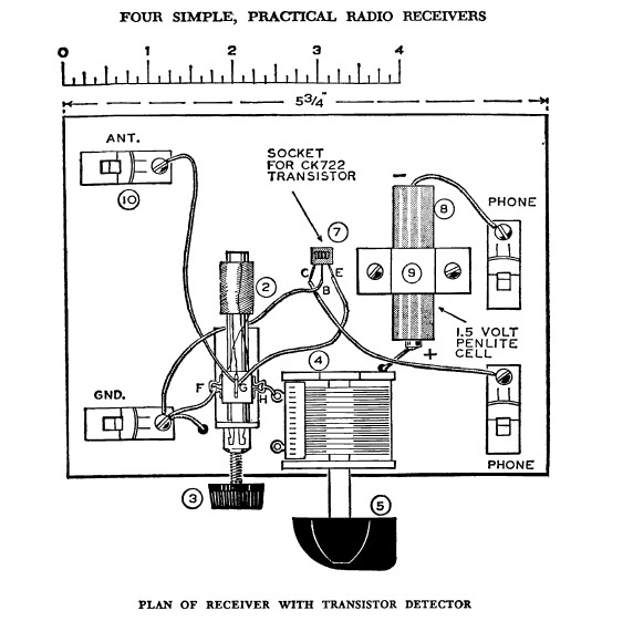
The set was wired according to this drawing. This is
important later in the story.
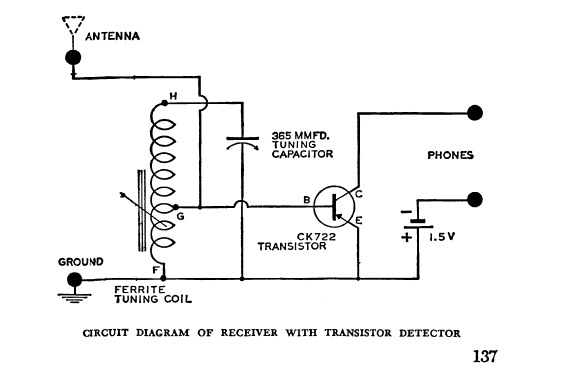
The schematic.
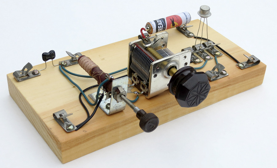
Here is the recreation.
The transistor is a CK722 / NTE102 Germanium equivalent. The battery
is an AAA skinned with a printed vintage wrapper. I am quite
impressed with this. This radio has ONE active component and a
battery. The selectivity is very good and our local station, WNPV
1440 AM, came in with plenty of volume.
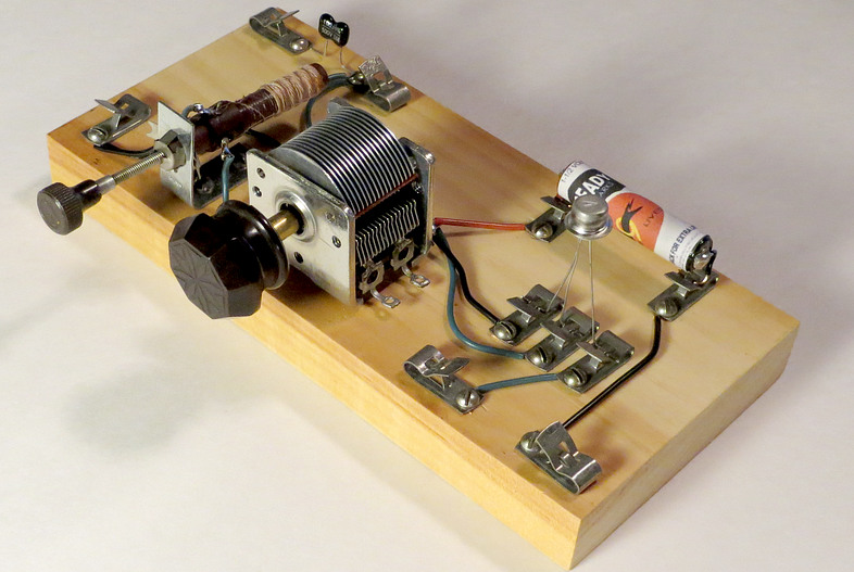
Eventually, an actual battery holder was added and the
transistor leads were labeled so different transistors could be tried in
the set.
If this radio works so well, why are there
so many other holes in the old base?
before you read on, so that the violin
is playing.
In spite of my efforts in
1966, the radio didn't work. Why didn't it work? I didn't
have an actual CK722 transistor, so maybe those guys at Ree
Electronics sold me the wrong part. And you probably need that
socket. The socket must have something in it that makes the radio
work. In other words, I didn't build it EXACTLY like the drawing, so
it didn't work.
Also, notice in the drawings that one of the connections
going to ground ends in a black dot. I don't know why Morgan drew it
this way. I think the wire goes under the base and comes back up
behind the variable capacitor. So maybe it didn't work because of
that. Maybe the wire had to be under the base for the radio to work.
Actually, there is a MISTAKE in both drawings. The red dot in
the top picture is supposed to be on the Collector, not the Emitter.
The Base and Emitter connections are swapped in the other drawing.
The schematic is correct. I may have fixed the radio by reading the
text and looking at the schematic, but I don't remember. It wouldn't
have made any difference at the time.
The main reason the radio didn't work was because no current
flows through the transistor until you plug in the headphones. The
headphones complete the circuit, and are the on/off switch. I didn't
have headphones. I had a crystal earplug. The crystal earplug didn't
conduct direct current through it, so the set was never "on". It may
have worked perfectly but I never knew it.
I could have dropped a 2.2K resistor across the headphone
clips, but I didn't know that. My sole source of radio
knowledge came from the Alfred P. Morgan books.
So apparently the set was partially dismantled and used for
other radio experiments. I still have the transistor I got from Ree
Electronics. I plugged it into the set, and it still works. It is so
beat up that I didn't use it for the picture.
That music is so sad.
Is that violin music still playing? On the next page
are two more crystal sets that didn't work at first.