|
Evolution of the
radio.
On October 8, 2014,
a guy named Greg emailed me out of the blue. He included seven
attachments in the email. Some of them were plans for a regen
"Twinplex" radio from a Lindsay publication. He wrote "Enjoy, let me
know how it works out for you."
I didn't get around to playing with the circuit 'til the middle of
January, 2015.
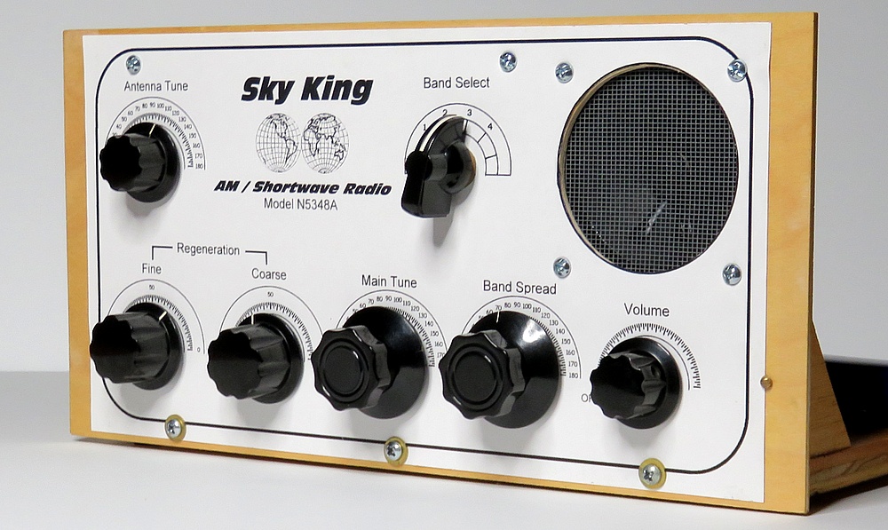
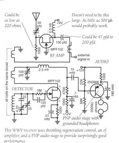
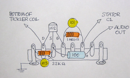
The schematic Greg sent me.
I altered it to receive the AM broadcast band. |
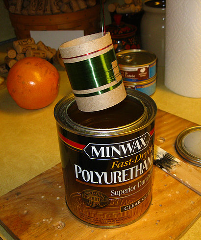
The article said to use a
toroid coil form but I didn't have any. I tried two straight
ferrite rod type coils but they didn't regenerate well.
|
|
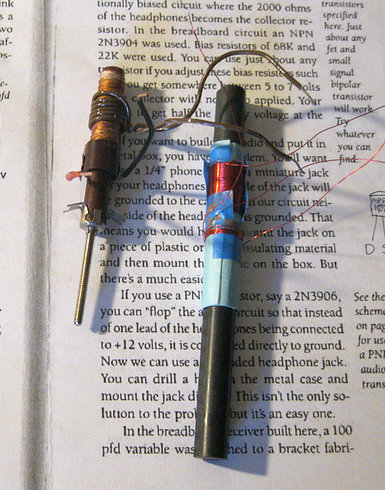
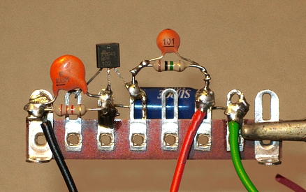
I used a plug-in coil made by
Elmer Osterhoudt. The results
were pretty amazing considering there was only one transistor. |
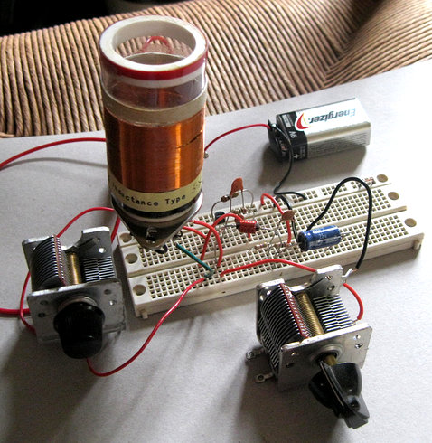
I decided to use the same type
of coil that is
used in the Peebles
Two Tube Regen Radio.
|
|
|
|
|
|
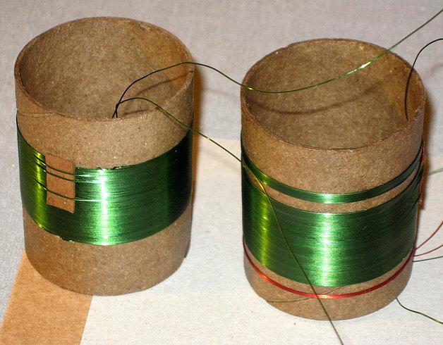
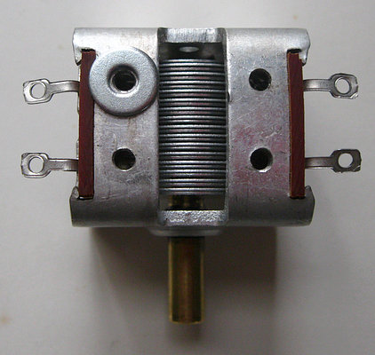
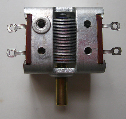
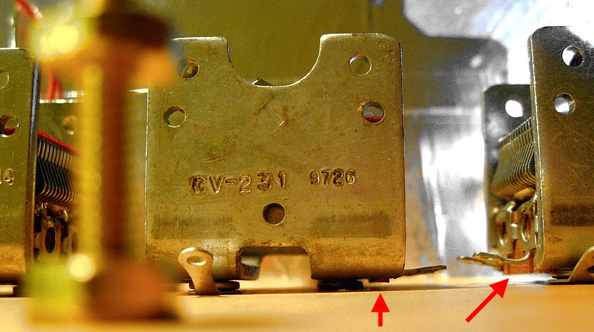
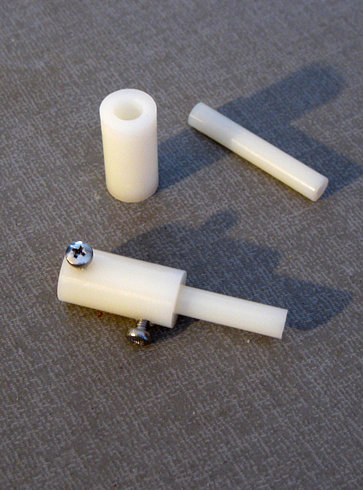
Antenna tuner coil on the
left. It would eventually be discarded. The main coil is on the
right. The red winding is for the RF amp but
it was also discarded. The top winding on the right hand is the
"tickler" coil which was eventually rewound.
|
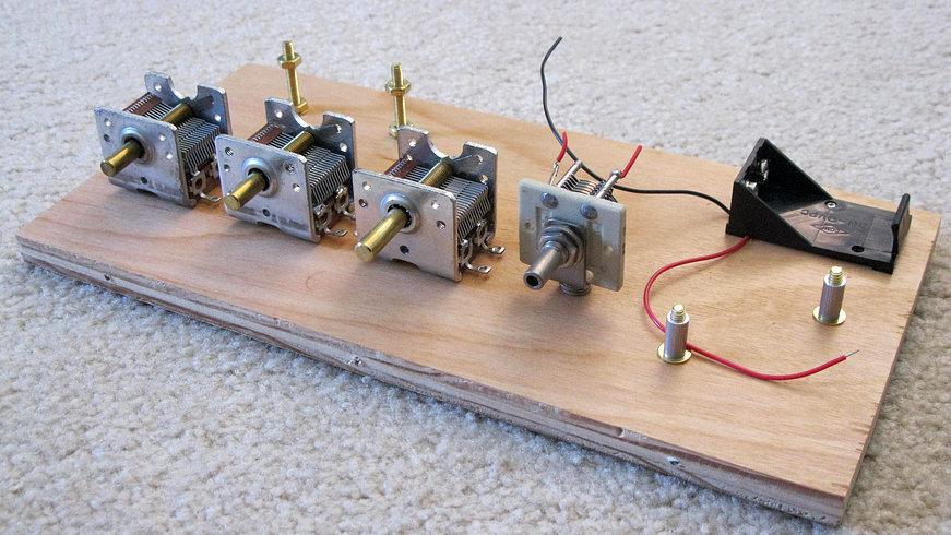
Here's the first version of the radio.
A Mike
Peebles antenna tuner and an external amplifier were used, and I tuned
to a corny old song for the movie. There is no RF amp.
The problem with the above setup is that you can't get your hands near
it or it throws off the regeneration. Or looking at it another way, once
you tune in a station, don't take your hands off the knobs!
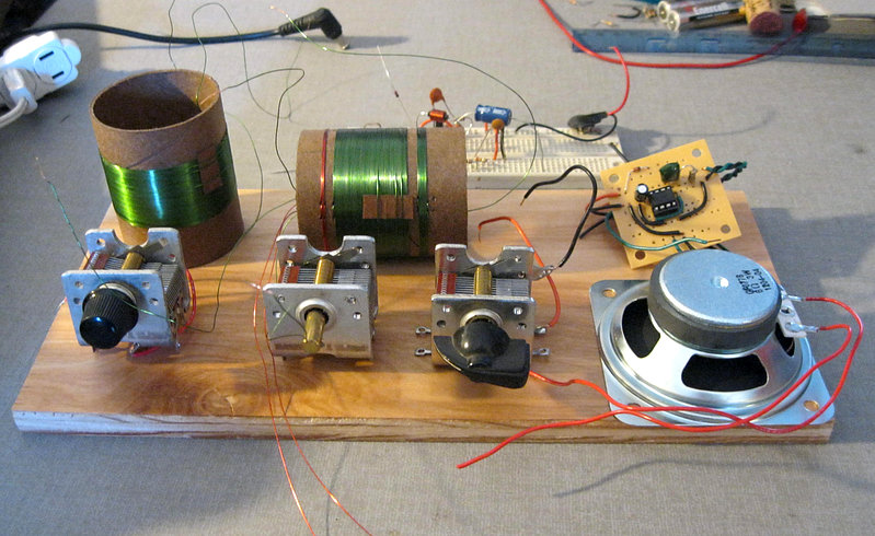
The next idea was to use the Lindsay "Twinplex" circuit to build a solid
state version of the Peebles Two-Tuber, with the antenna tuner and
amplifier on a single chassis.
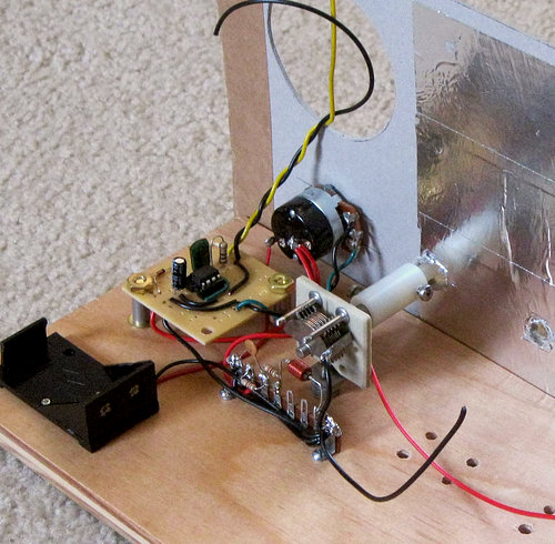
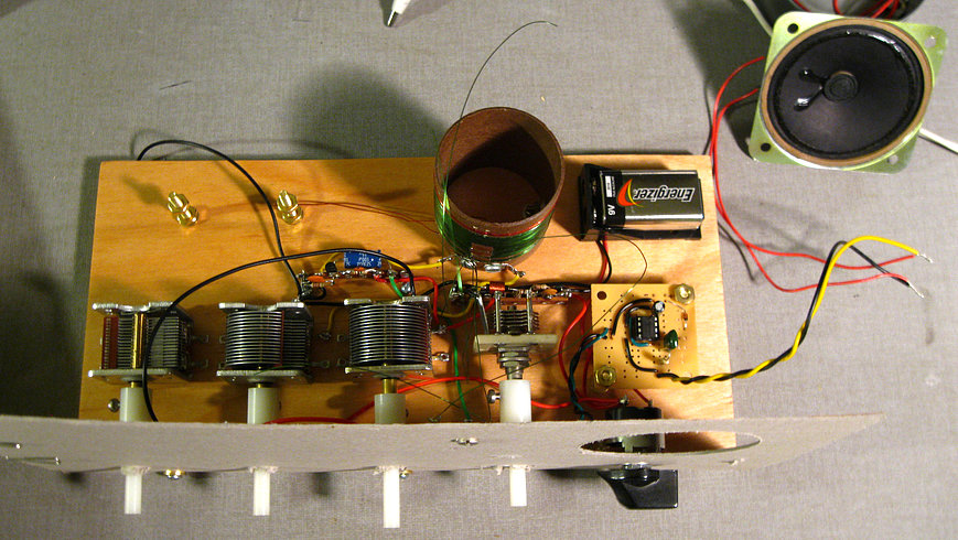
It was time to make a
setup that would be easier to work with, but semi-permanent so
it could be changed.
|
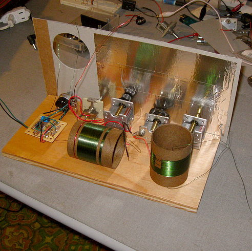
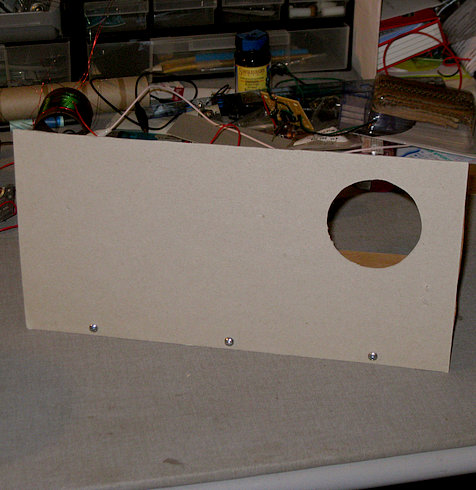
...Therefore the front panel was made of cardboard with aluminum tape as
a shield.
In these pictures the
audio amplifier has already been built. I ran into trouble with this
very board while building the
Ferrite
Ferret
and this working unit was
left over from that project.
|