|
Mike Peebles'
Two Tube Regen Kit mashup |
 |
|
|
| |
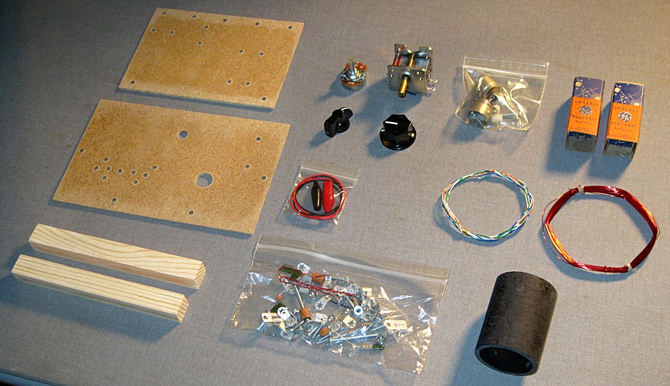
Here are the parts that came with the Peebles two
tube regen kit.
|
|
|
|
|
|
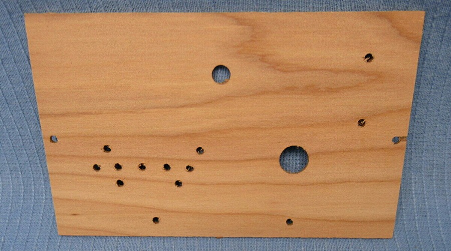
Years ago, the panel and base were made of plywood.
I found this picture on ebay. It was for an older version of the kit. |
|
|
|
|
|
|
|
|
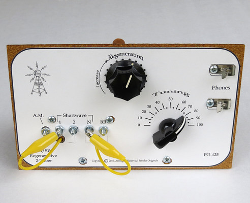
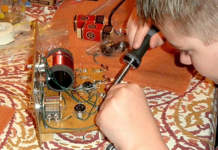
Here is a completed kit. This was built by on
11/15/2015 by grandson Matt Knoebel as a school project.
|
|
|
|
I spent days on mine. Matt built his in one sitting. |
|
|
|
|
|
|
|
|
|
|
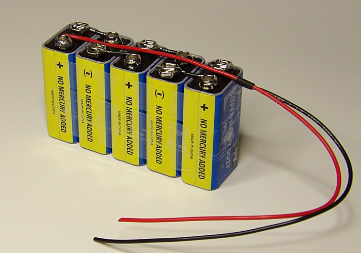
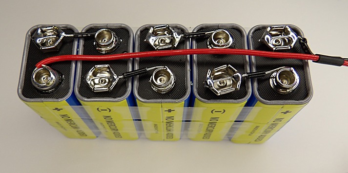
The 45 volt battery. |
There are several ways to connect 9 volt
batteries together, but this is the cheapest. All it takes are
some dollar store batteries, a soldering iron, some scrap wire and plastic
tape. A piece of clear packing tape went over the top after this
picture was taken so they don't short out.
"NO MERCURY ADDED" must have been thought of as a selling point,
when the actual selling point was that they were A DOLLAR. You
used to get two for a dollar when they sold Sunbeam brand.
|
|
|
|
|
|
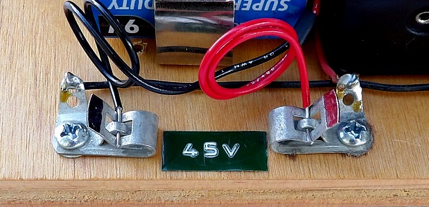
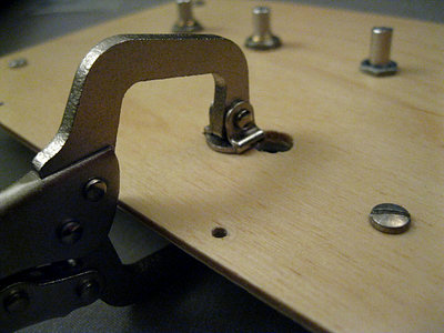
| The battery connections are Fahnestock
clips. This allows easy replacement of the battery. You can also
take the battery pack out and use it in a different radio, or
use a different battery in this radio. |
|
|
|
|
|
|
|
|
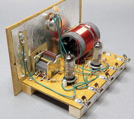
Looking at the previous page and the above
pictures, one would think this went together in a
fairly straightforward way.
All you have to
do is transfer the kit parts to another wooden base. What could go
wrong? Well... for example: |
|
|
|
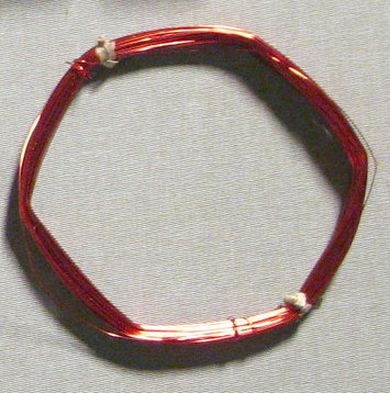
Here is the hank of wire that came with
the kit.
It's 58 feet long! |
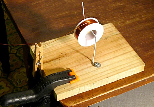
...and here is my coil winding jig. It's just a piece of coat
hanger to hold the spool
and a clothespin to put tension on the wire as it's wrapped
around the coil form. |
|
|
|
The little coil winding jig
can't handle a "hank" of wire. It's very important that there
are no kinks or twists in the wire. What to do?
I got this
great idea to place the end of the wire in the clothespin and
very carefully unroll the hank. I walked from the kitchen (where
I was winding the coil) into the living room, then turned into
the dining room, walked through the dining room and into the
office at the end of the house, unwinding the
hank with great care. I then went back into the kitchen.
When I got back to the kitchen there was no wire in the
clothespin. There was no wire on the kitchen floor and there was no
wire on the living room floor! About ten feet from the office I found a red bird's nest. The wire
had quietly ka-fwanged out of the clothespin, shot through the kitchen and the
living room and ended up a tangled wreck. DOH!! Ruined.
Note: Mike Peebles now supplies the wire on a spool and sent me two
free spools with my next order. |
|
|
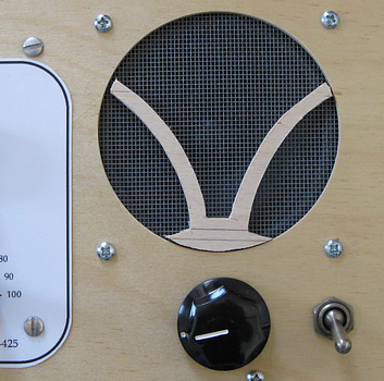
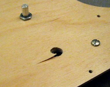
Next, I tried to get fancy with the speaker
hole. I cut a pattern
out with a coping saw. When it came out asymmetrical I
got
rid of the pattern, but then the hole wasn't round. Crap!! |
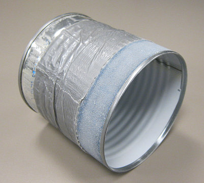
To make the cutout round, it was sanded with
a tin can
wrapped in sand paper held on by duct tape. |
|
|
|
DANG! |
Waiting for the glue to dry.... |
|
|
|
|
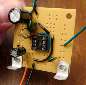
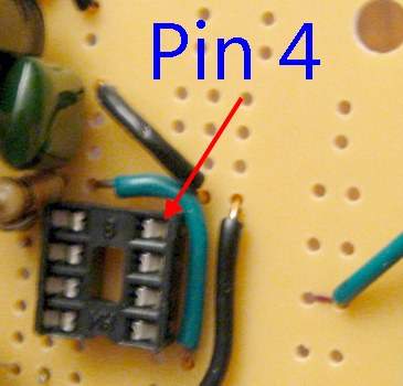
| This is the first
board for the LM386 amplifier. It didn't work, unless you
consider the radio going "putt-putt-putt-putt-putt-putt-putt" to be
"working." I could not figure out what was wrong with it.
The two black wires belong on pin 4 of the socket needed to be
moved down. No matter how many times I looked at the board I
didn't see that they were in the wrong place. Also, notice the
"shiner" on the orange wire. I took it apart and rebuilt it. |
|
|
| |
|
|
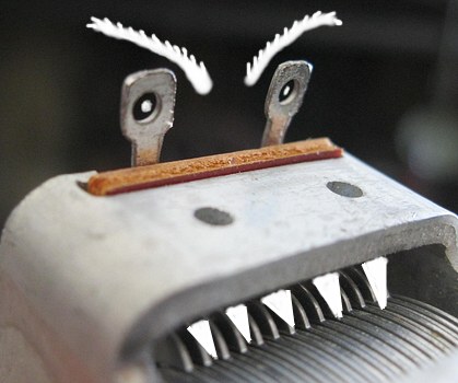
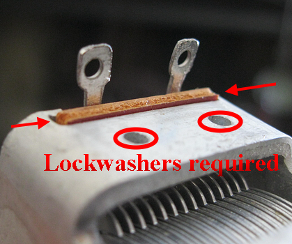
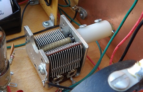
| The tuning capacitor monster struck while I was asleep. The radio had been sitting
untouched overnight. The next day I found the
tuning capacitor had shorted out! You could
hear the plates touching. I wrote to Mike Peebles.
He
wrote a paragraph back in UPPER CASE (yelling) and said I didn't
put lock washers or spacers under the capacitor as he said to
do in
the instructions. When I
tightened it down, the fiber insulator was pushed upwards and
distorted the stator. He knew what happened without
seeing the radio! I should hang a sign on the wall
that says, "Mike Peebles is watching you."
Realigning the stator plates and putting lock washers under the
capacitor while it was wired in place was frustrating to say the
least. |
|
|
|
|
|
|
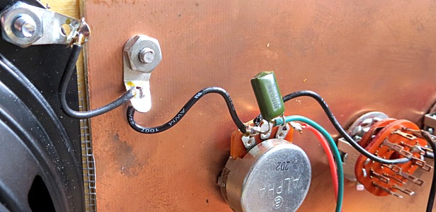
| They say you shouldn't daisy-chain your
grounds. I wanted the speaker frame to be at ground, like the
front panel, so I connected a wire to the front panel.
There is really nothing wrong with that, except that I had this
great idea to pick up a ground for the audio amp from the
speaker frame. Later, I changed the speaker. Because of the daisy-chain,
I created a short
circuit in the radio and lost the ground connection to the audio
amp, rendering the whole setup completely inoperable. |
|
|
|
|
|
|
There were other issues, too. For
instance, I ruined the first shaft extension for the tuning cap.
My regeneration control had a reverse action and the connections
on the back had to be swapped, and I had to print out the front
panel about ten times before the spacing was correct.
The very last thing I did was to connect
the battery for the audio amp, only to find there was no place
to put it.
I've found that when building these small sets there always seems to
be fix or a workaround for almost any problem. Especially when
you cause them yourself. |
|
|
|
|
| |
|
|
| |
| |