|
The
OZARK PATROL |
 |
|
|
|
CONSTRUCTION |
|
The kit doesn't come with any
instructions. They must be downloaded from the 4 State QRP
website. On the first page it states that construction
should take about two hours. Under "First Steps" it says to
organize the parts first. Don't get the idea that you're
going to actually be done in two hours. From the time you
open the box till the time you've got your parts counted an
hour will have gone by. |
|
|
|
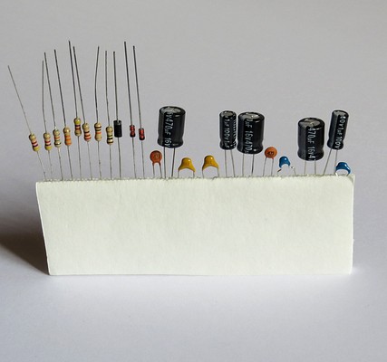
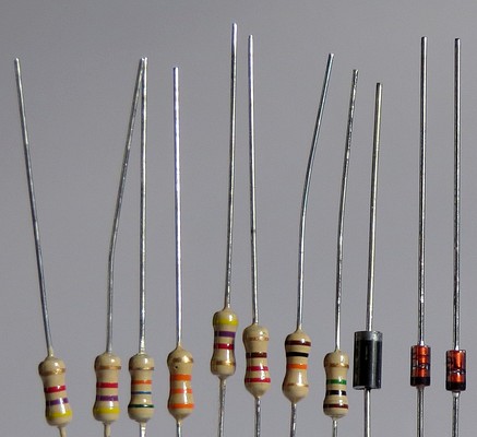
Since you have to count the components, line
them up in the order they will be used, then double-check as
you solder them in.
If you examine the parts closely you might see oxidation on
some of the leads. Instead of being bright silver they may
be gray. This must be removed if you want a good solder
connection. Just pull them through a small piece of "Scotch
-Brite" or fine sand paper before you solder them in. |
|
|
|
|
|
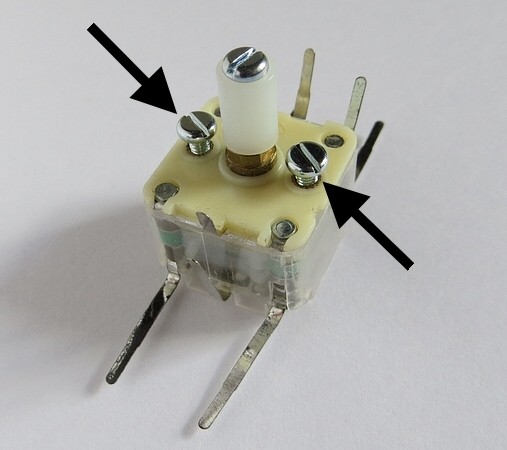
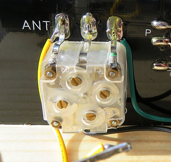
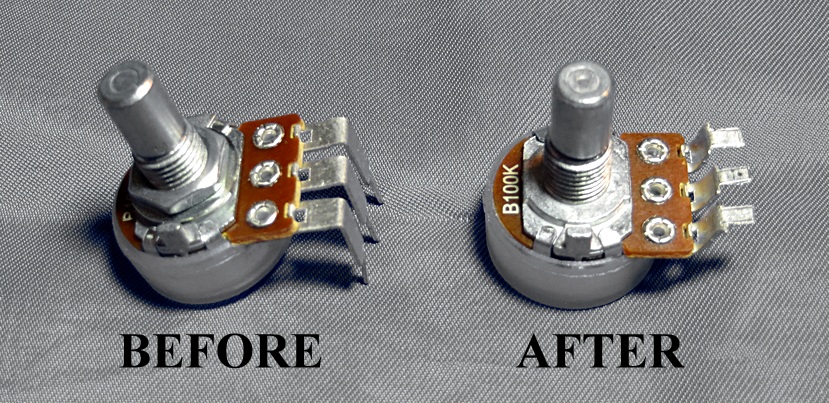
When you pick up the variable
capacitor, the first thing you do is turn the shaft; it's
just human nature. DON'T DO IT. If the screws provided to
mount the capacitor are turned all the way in, back them out
or remove them. OK, now you can turn the shaft. To tighten
the shaft extension, hold the shaft with a pair of
needle-nose pliers. |
|
|
|
|
|
|
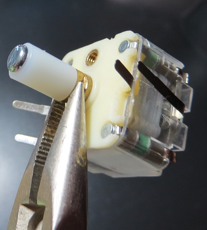
While installing the capacitor, spread out the four tabs on the back corners and cut
them off. Push all the other tabs forward. |
|
|
|
|
It looks like this when you're done. |
|
|
|
|
|
|
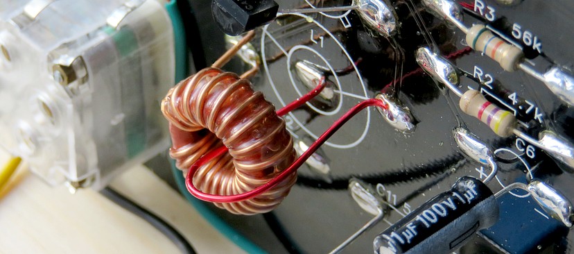
The first part to be soldered
to the board is the coil.
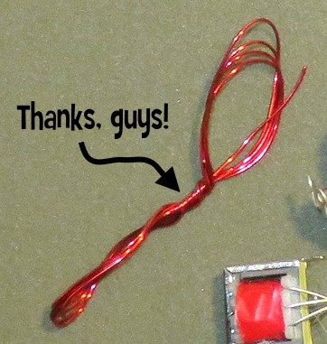
The 22 gauge magnet wire supplied was rather twisted up. It
was impossible to get the kinks out, so I used my own wire.
I also gave the coil two coats of polyurethane, so it ended
up being the last part installed instead of the first.
Someone wrote in and asked my if I used a brush for the
polyurethane. No, I dunked it in the can. |
|
|
|
|
|
|
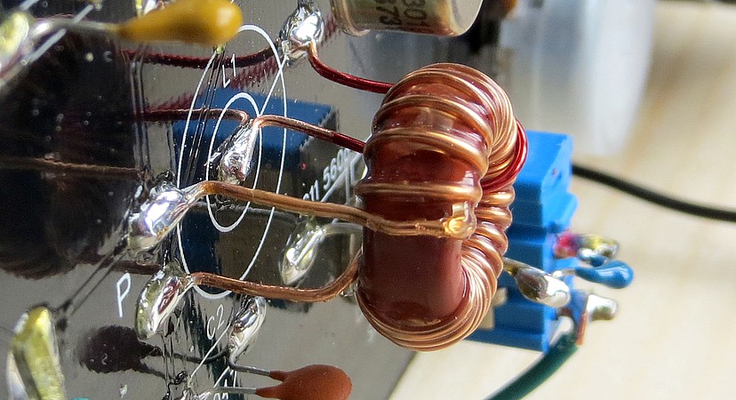
The instructions say to mount the coil
flat, but I raised mine away from the grounded panel. For
all practical purposes, the magnet field lines in a toroidal
coil are inside the coil and should have no unwanted
coupling with the panel, but ya never know! Everything I've
learned about tuning coils told me to never put the coil
near a grounded metal object |
|
| |
|
|
|
My set had too much feedback.
I put some space between the coil and the tickler
wire to improve the action of the regeneration control. |
|
|
|
|
|
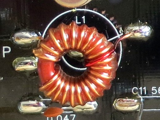
| Here's another coil. Winding the coil
can be difficult because it is so small. The length of the
wire required is about fourteen inches. The hank of
wire that comes with the kit is four feet long. Cut the wire
in half and you will have plenty, but won't have to thread
four feet of wire through the toroid twenty times. |
|
|
|
|
|
|
|
|
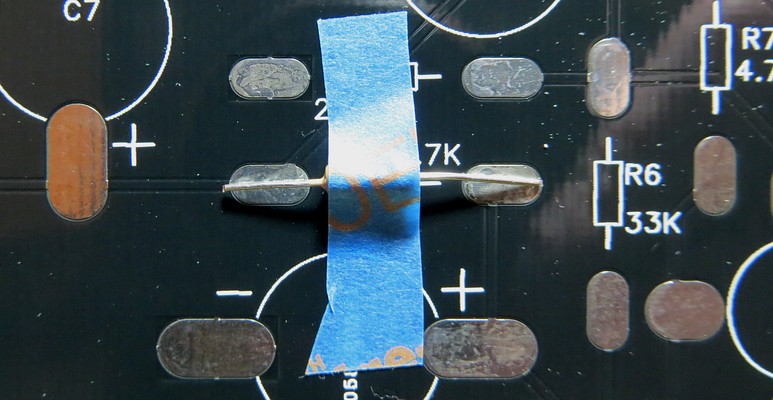
The manual gives
instructions on how to solder the parts in, but I didn't follow
them. From the way I saw it, you need three hands.
My third hand was a strip of painter's tape. I used the same piece
over and over. Here is the first resistor about to be soldered. |
|
|
|
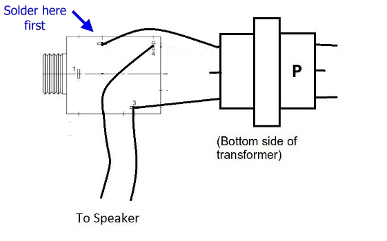
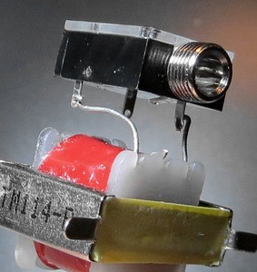
Now we come to
another reason you will not complete the kit in two hours. The
headphone jack is mounted just a little
too close to the transformer for easy assembly. The
wiring diagram on the left shows the bottom of the transformer and
the side of the jack. In reality, the bottom of the transformer
and the front of the jack both point in the same direction.
|
|
|
|
|
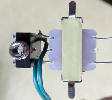
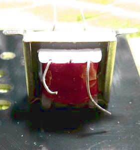
NOTE: The side of the transformer that is
soldered to the front panel has the letter "P" stamped on
it. The jack is connected to the other side.
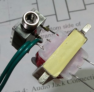
This is one way to assemble the two
parts:
1. Cut off the center leads from both sides of the
transformer.
2. Wire the leads according to the diagram, but with the
jack pointing down. Bend and cut the leads after making a
test fit.
3. Push the leads into the holes in the jack terminals and
crimp them.
4. Solder the connection shown upper left in the
diagram. This will hold things together.
5. Crimp the speaker wires around the jack terminals and
solder the remaining two connections.
6. Insert the jack into the front panel and attach it with
the lock nut. Squeeze the two components together until the
transformer sits on its solder lugs.
Welp, there goes your two hours. Finished yet? |
|
|
|
|
|
|
The primary side of the transformer is marked
with the letter "P." |
|
|
|
|
|
|
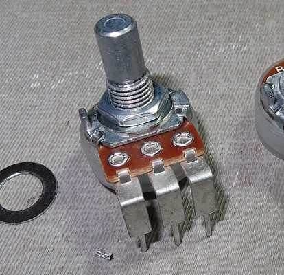
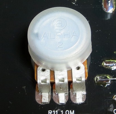
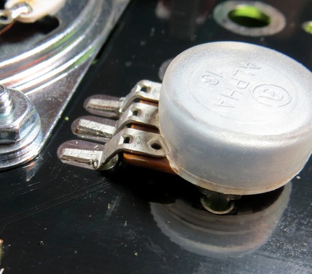
The terminals on the pots face the wrong way! The
instructions say to just bend them. Grab a decent pair of wire
cutters first. |
| |
|
You'll have to bend them AND trim them to make them
fit. Add another hour. |
| |
|
|
It took me over six
hours to build this, so don't feel bad if the "two hours" has come
and gone. Who wants to slap it together in
two hours anyway? Spend an hour on it, put it aside, then come back
to it later. Don't forget to unplug the soldering iron.
|
|
|
|
|
|
|
If you get the "correct" parts, just bend the
terminals down like it says in the instructions. |
|
|
|
|
|
Make sure the terminals are touching the solder
pads. |
|
|
|
|
|
|
|
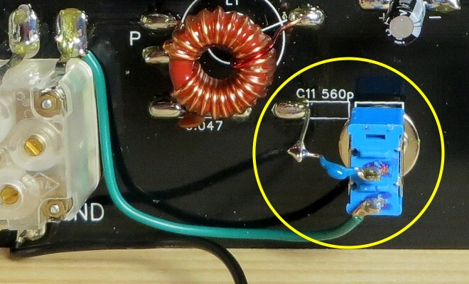
The band switch was
wired per the instructions, but it works backward. The low band is
up and the higher band is
down. No, I didn't put it in upside-down, but I should have. It
drives me crazy. It's a simple toggle switch that puts
capacitor C11 (560p) in parallel with C1 (main tuning). When
you install your switch make sure the ON position is DOWN.
The regen control has a reverse action.
You turn it full clockwise, then turn it counter-clockwise to add feedback.
The instructions say to do the opposite. The instructions
also say to turn the volume control fully clockwise when you
turn on the radio, so the radio is at maximum volume and at
maximum regeneration as soon as you turn it on. I hope
you're not wearing headphones. It's probably a mistake in
the manual, or even a practical joke. |
|
|
|
|
| |