|
 |
 |
|
|
|
|
| |
|
|
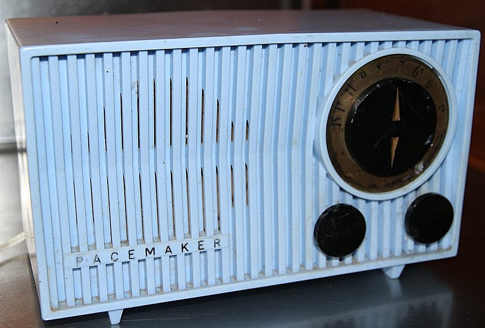
| Let's get back to the
cabinet, but before we do, check this out. It's a Collier
and Beale Pacemaker "Petite" from 1955, made in New Zealand. |
|
|
|
|
|
|
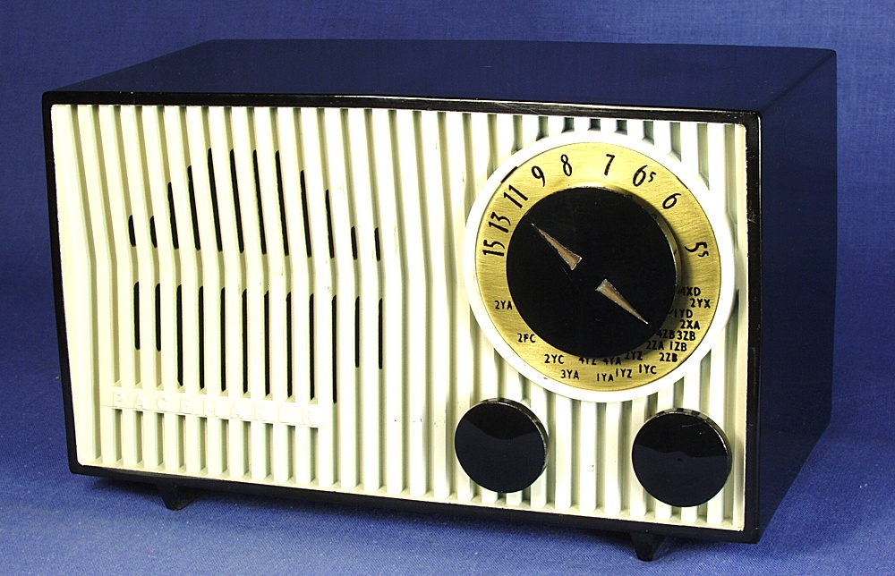
Here's another one. This photo was sent in by
Robert Lozier.
|
Website |
|
|
|
|
| |
|
|
|
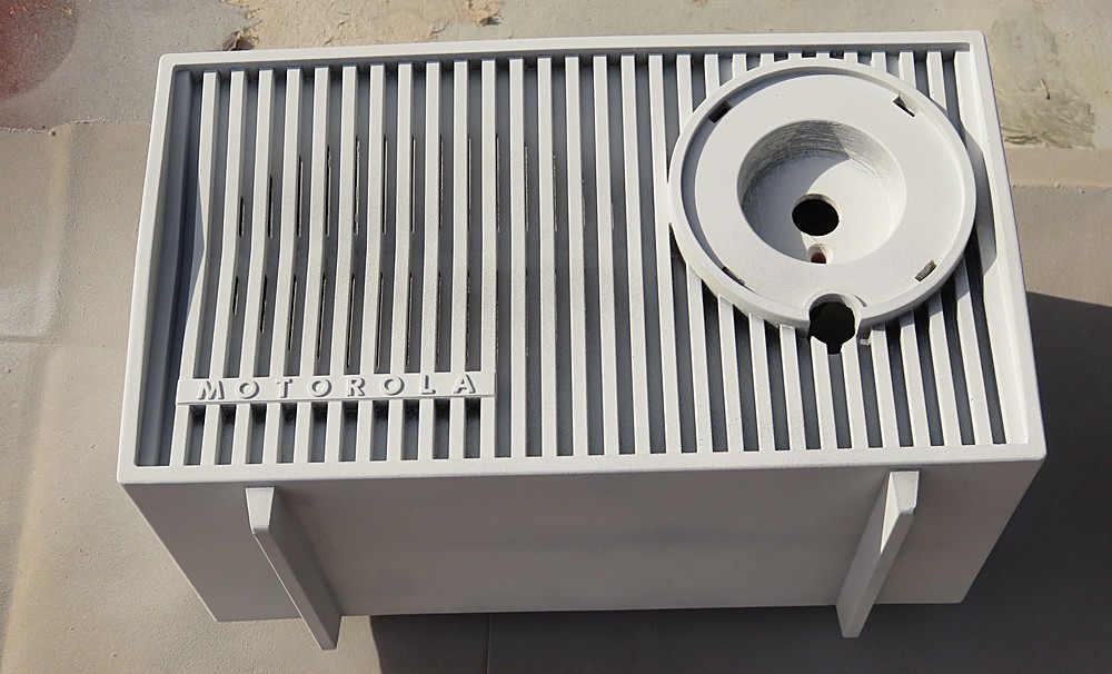
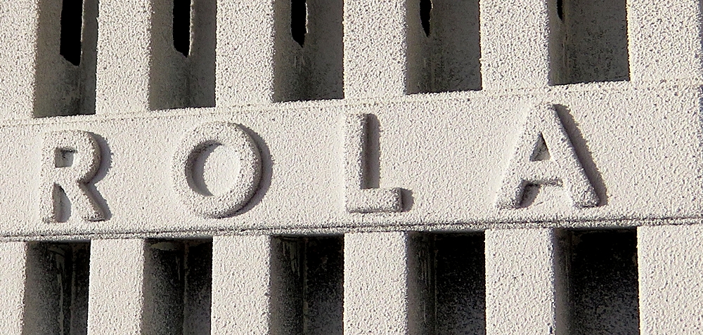
The cabinet now gets a coat of white primer.
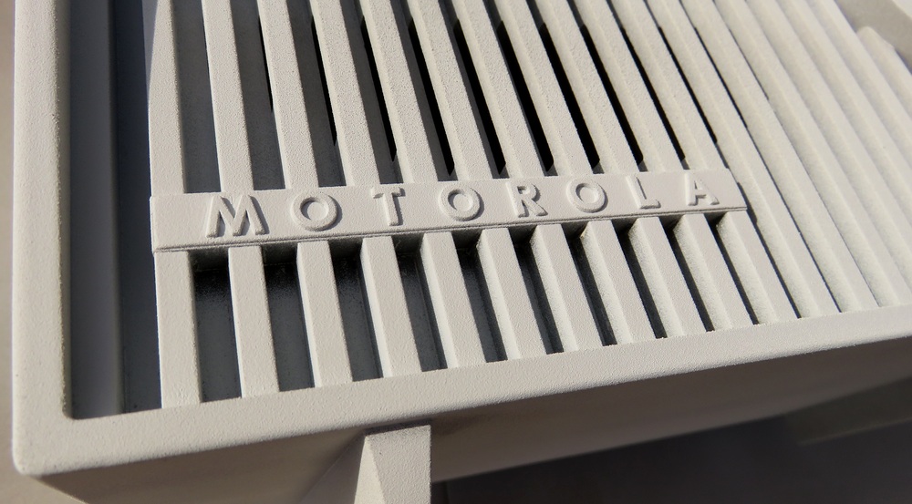
That looks really good. Look how crisp the word "Motorola" came out. |
| |
|
|
|
Yes indeed! Very clean and crisp! It's ready for the
paint. Wait a minute.... |
| |
|
|
Mother of God!!
|
I became apoplectic.
|
The radio cabinet feels like it's made out of sand paper!
Now the paint has to come off again. |
Oh well.
|
|
|
|
|
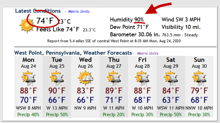
Here is what I think the problem is.
It's late
August in Pennsylvania. It's chilly out in the morning, but the
humidity is too high for spray paint. |
|
| |
|
|
|
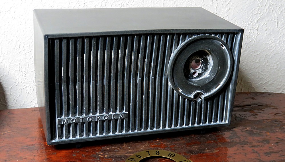
Now it will sit on this shelf until the weather
changes. |
|
| |
|
|
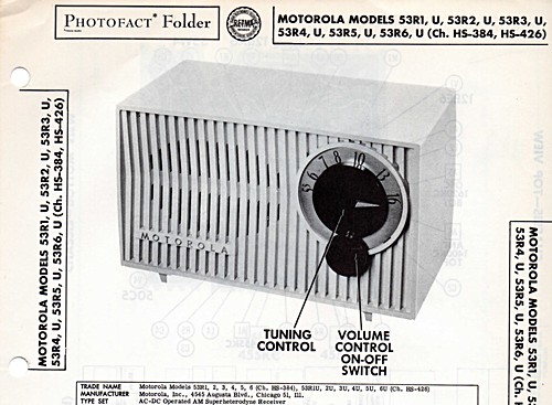
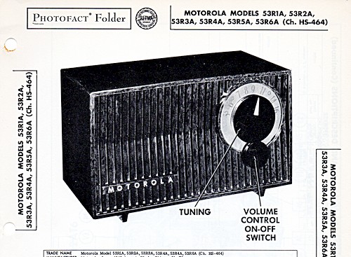
There are two Sam's Photofact Folder's for the
53R, and the pictures on them look like a before/after shot of this
radio.
Click on either picture to download the Sam's Folder. |
|
| |
|
|
|
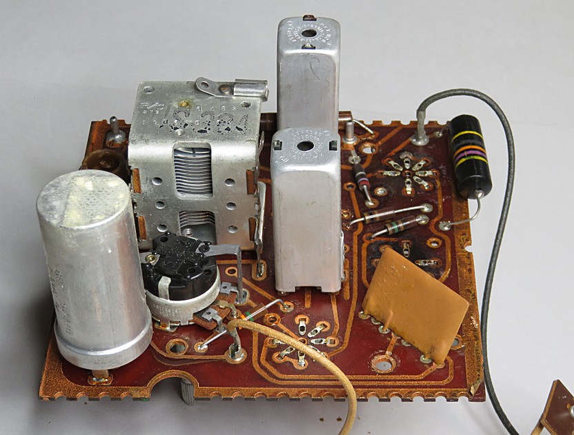
Let's take a look at the radio chassis. The
parts are mounted on a double-sided circuit board. |
| |
|
|
|
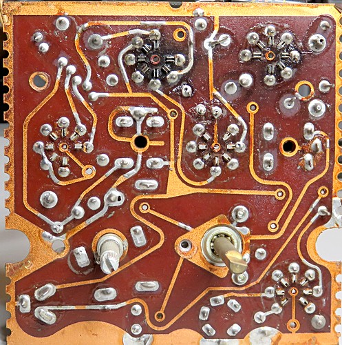
The circuit board is called a PLAcir, short for
"plated circuit." Later, we would call them "printed circuit"
boards. |
| |
|
|
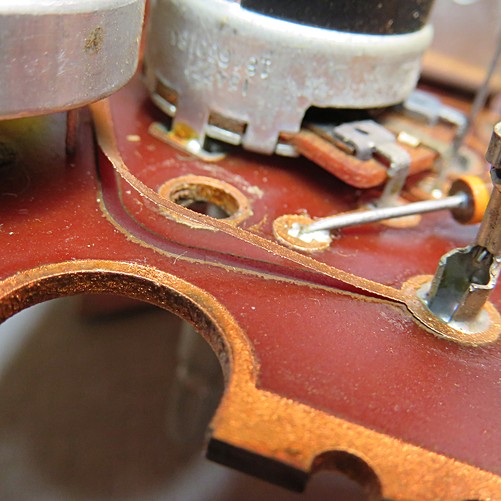
Notice the scorch marks around the
tube "sockets" on the top-left. The circuit board
is made of
paper fibers in phenolic resin and tends to burn from the
heat of the tubes, especially the 35W4 and 50C5 tubes.
Not everything made "back then" was made to last. This radio
was made as cheaply as possible. It doesn't even have real
tube sockets. With enough use, the 35W4 and 50C5 will
burn the board under them to a crisp and it will
begin to fall apart. In the right-hand photo, one of the
copper traces has lifted off the board, and that part of the
board doesn't even get hot. |
|
| |
|
|
|
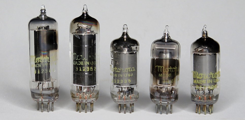
35W4 |
50C5 |
12BA6 |
12AT6 |
12BE6 |
|
|
The 35W4 is the
rectifier tube. The 50C5 is the audio output tube. They both
run very hot, and the glass reaches a temperature of 428°F. These two are what
has scorched the circuit board.
All of the tubes tested "new" except the 50C5, which was at
87%. I tried to figure out how much this radio was used
based on the 87%, but it's really not possible. First of
all, you'd have to know exactly how long the tube would
last. Let's say it's 2000 hours. You can't take 87% of 2000
because the decrease may not be linear. It might take 50
hours for the performance to go down 10%, but
another 500 hours to reduce another 10%.
The 2000 hours tube life was just a guess, anyway. Eventually I gave up trying to figure it out. |
|
|
| |
|
|
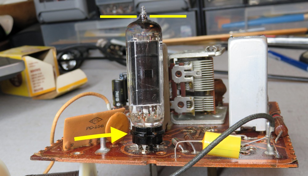
| I started to add a real
tube socket, but it elevated the tube and it interfered with
the back of the radio. Of course, the tallest tube needs to go into
the socket. To
make it fit, a hole would have to be drilled through the
circuit board to drop the socket into, and I'm not going to
do that. Haha... I could also drill a hole in the back of the
radio, so the tube sticks out. |
|
|
| |
|
|
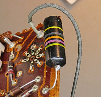
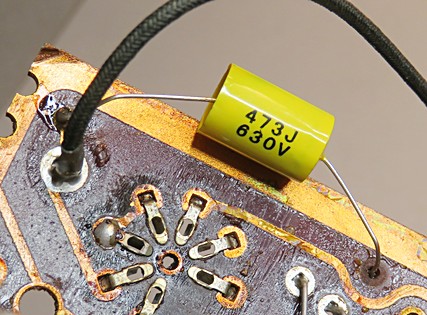
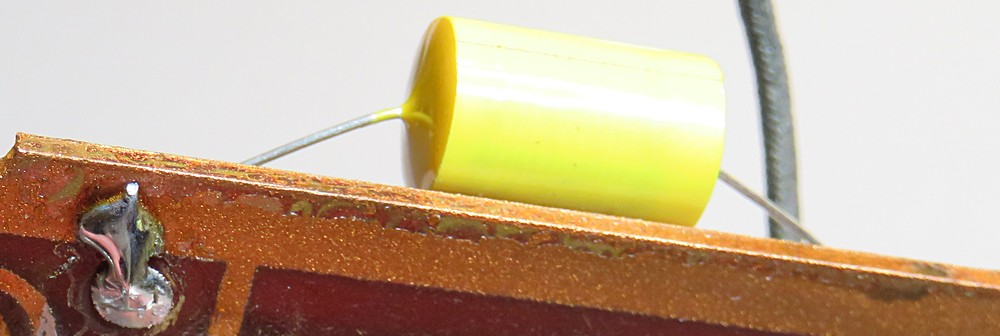
I decided to replace the funny black thing with
a yellow thing. It's a Sprague brand capacitor, sometimes called a "Bumblebee."
Reading the colors from the bottom-up, they are 4, 7, 000,
20%, 400, so the rating is 47000 picofarad +/- 20% at 400
volts. |
|
| |
|
|
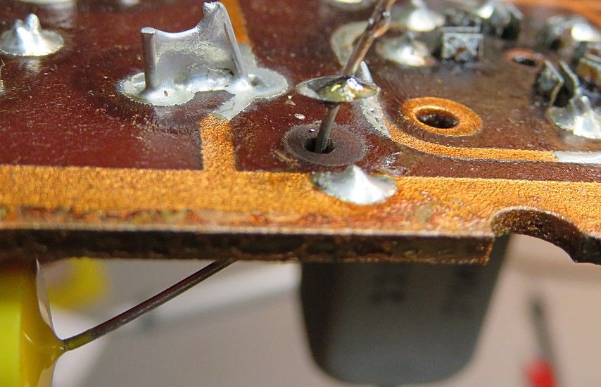
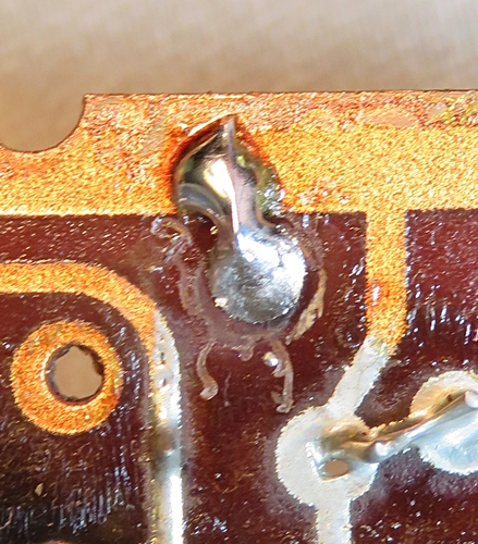
I ran into something very strange.
When the wire from the yellow thing was inserted, the
little copper pad popped off the circuit board.
That's OK, it doesn't seem to be connected to anything on this side,
so the connection must be on the other side.
|
|
| |
|
|
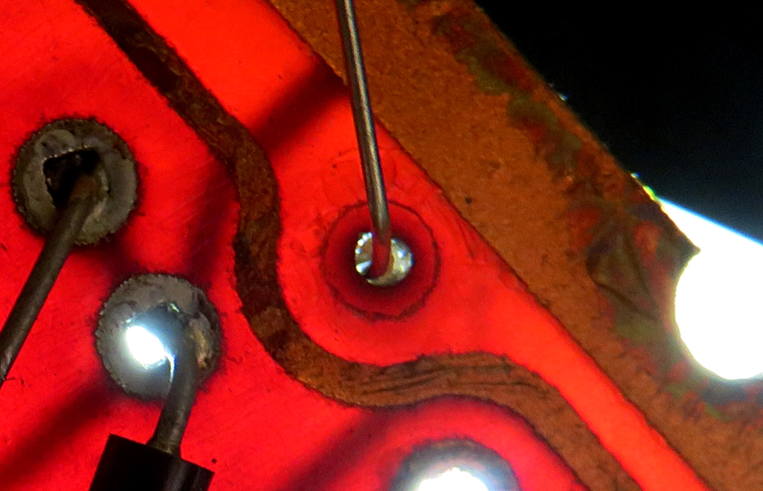
Wrong. When the board is held up to a strong
light, you can see there is no connection on the other side, either.
This was never connected to ANYTHING! |
| |
|
|
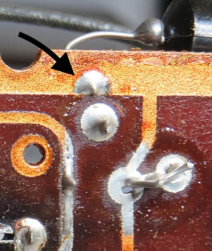
| Oddly enough, there was a blob of
solder on the circuit board which
served no purpose. Looking at the schematic, I saw the
capacitor should have been connected there. I bent the lead
over and soldered it. |
|
| |
|
|
| This capacitor is
connected across the AC line and isn't really needed for the
radio to work. Those "Bumblebee" capacitors are notorious
for bursting open. They're oil filled and are sealed in
plastic. They work great in amplifiers, but placing one
across the AC line probably wasn't a good idea. I wonder if
Motorola, as a quick fix, omitted the solder connection
during assembly. |
|
|
|
|
| |
|
|
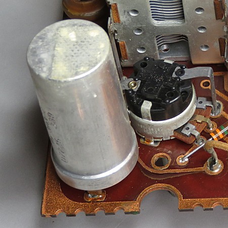
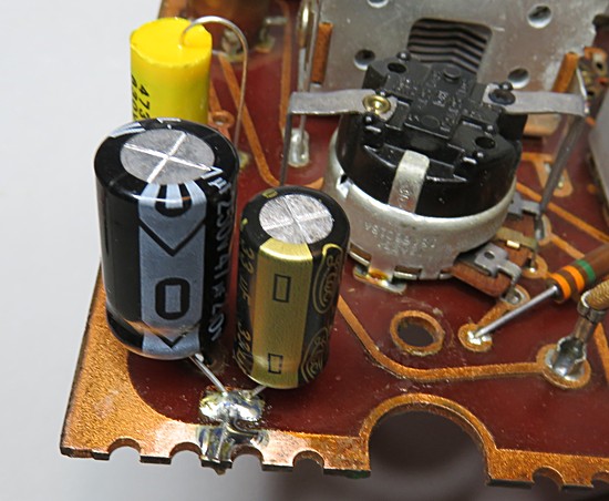
The filter caps were replaced. (There were two in
the metal can.)
Every time the soldering iron touched the circuit board, the copper
lifted off. It was reinforced along the edge with
solder. |
| |
|
| It seems
Motorola came out with the plated chassis the year before,
in 1952. Read about it |
here. |
|
|
| |
|
|
|
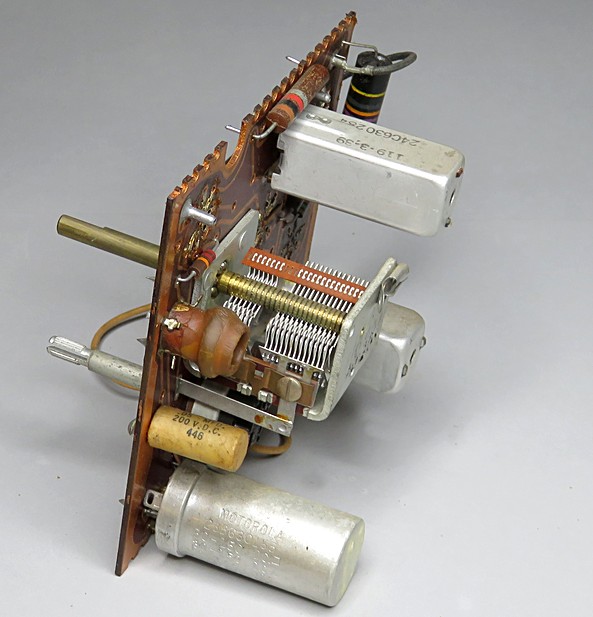
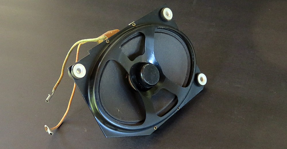
Check out the speaker! See the round thing in
the middle? |
| |
|
|
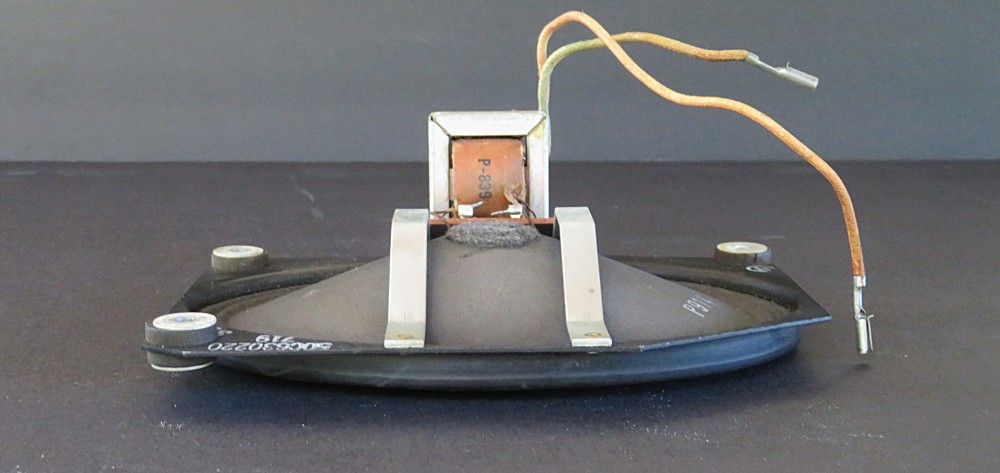
Motorola put the speaker magnet and voice coil in FRONT of the
speaker. (The silver and tan transformer isn't part of the speaker.)
This allowed Motorola to make thin radios. They even made a clock radio you could hang on your wall.
So what's the big deal? Somehow, the voice coil needs to
work in reverse. Instead of pushing the paper cone from
behind, it has to pull it forward. Otherwise, most of the
sound would come out of the back of the radio. |
|
|
| |
|
|
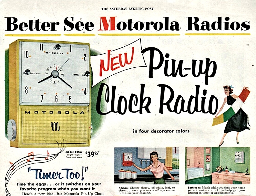
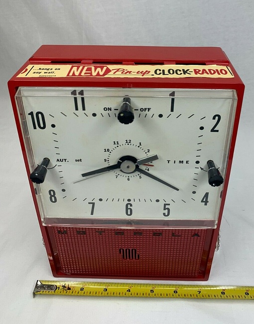
Here's the radio that hangs on the wall, thanks
to the new speaker design. Model 52CW.
Click on the picture to see the entire advertisement.
Note: it's impossible for the hour hand to be pointing directly at
the 8 if the minute hand is showing twenty-some after the hour.
Didn't they notice this? |
| |
|
|
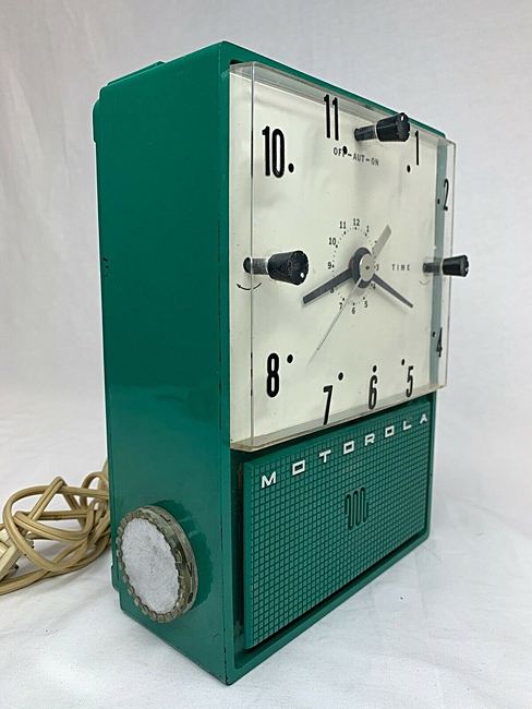
Here are actual Pin-Up Clock radios. Notice the
time on the clocks is the same as on the advertisement.
Even though you could "pin it" up, you still had to find a place to
plug it in. It is not battery powered. |
| |
|
|
|
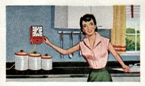
How it's shown in the advertisement, and how big it
would really look. Hahaha, they did this stuff all the time with
these drawings. |
|
Notice, there is no electrical cord in the
original drawing. When you got it home and went to "pin" it up, there may
have been a slight problem.
It's twenty-two after seven (and six seconds), according to the clock.
The sun is out. If it's summer it could be either AM or PM. Which do
you think it is? |
|
| |
|
| |
|
|
|
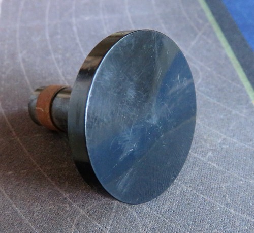
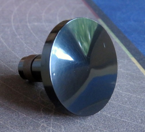
Enough about the speaker and the wall clock. Back to the 53R radio, the knobs are made of plastic and were easily
polished
up. |
|
Now let's do some painting. |
|
|
|
|
| |