|
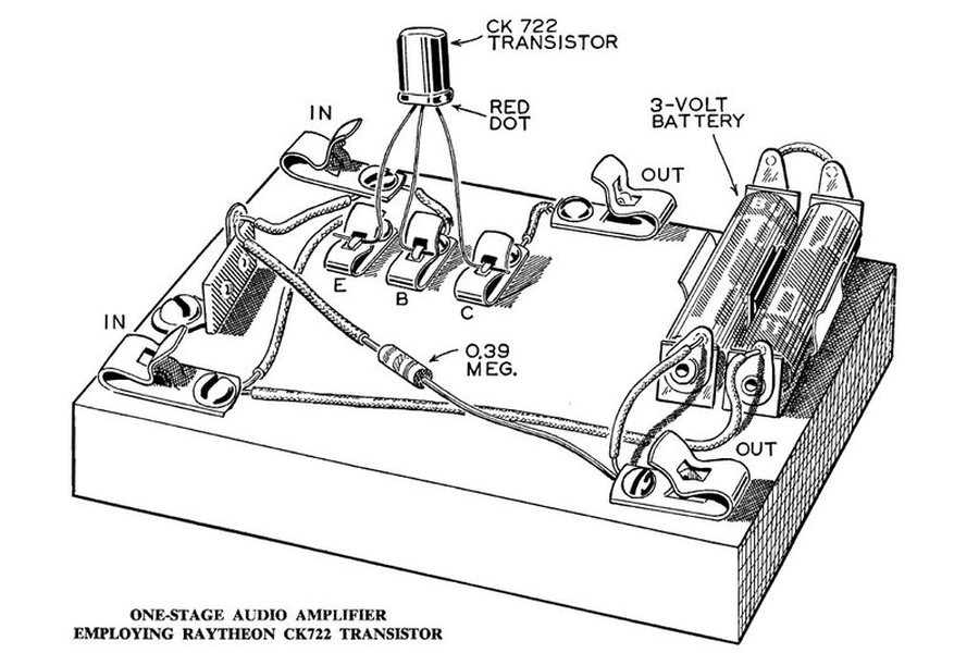
Alfred P. Morgan One Stage
Audio Amplifier |
 |
|
|
|
|
|
|
|
|
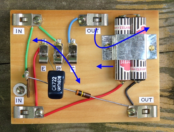
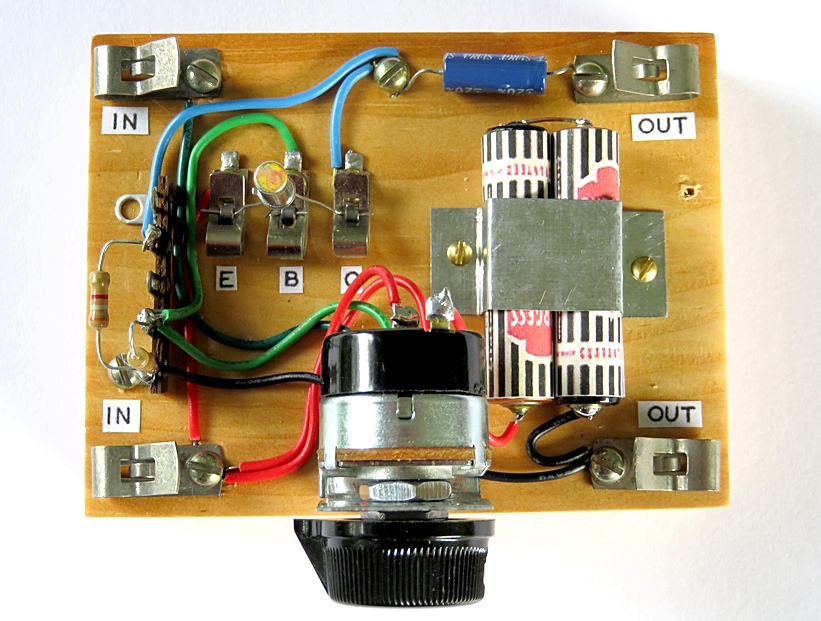
Now let's think about this.
֎
Why do we have a resistor with long leads floating in the
air when it can swap places with the green wire?
֎ Why have an
output clip in the middle of the board when it can be moved
to the right to match it up with the other one?
֎ Why have 3 volts DC
going through your super sensitive high impedance
headphones??
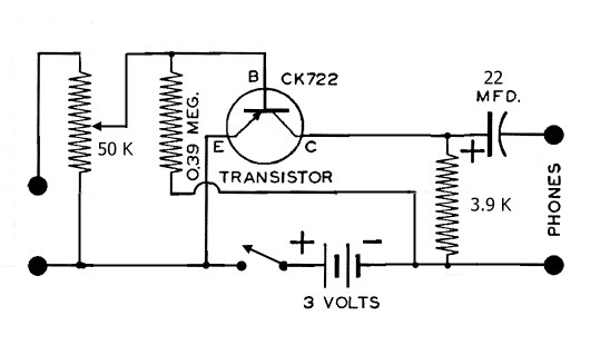
We can use a resistor in place of the headphones, then pick
the audio off the collector of the transistor with a capacitor.
That would get the 3V DC out of the headphones but then we
need an on/off switch. Since we need to add a switch, why
not add a volume control? |
|
|
|
|
|
|
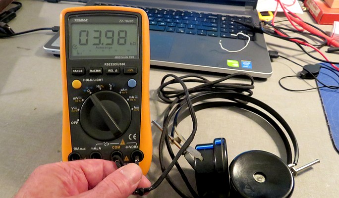
What value resistor should be used to replace
the headphones? I don't have any real knowledge of
electronics, so I can't calculate it. I do, however, have a
cool meter my buddy Joe gave me for Christmas. The DC
resistance of the headphones is about 3.98 K
Ω, so a 3.9K resistor will take
their place. (Those headphones are supposed to be 4K.
Somebody owes me 20 ohms.) |
|
|
|
|
|
|
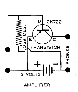
Original schematic and the new schematic with
the four parts added. |
|
|
|
|
I had to work carefully because Alfred P.
Morgan may be watching. Elmer Osterhoudt as well. I recently
found out that the "O" in Osterhoudt is a long O. For years I
have been calling him Ah-sterhoudt instead of Oh-sterhoudt.
He spoke to me from the grave by way of one of his "MRL
Radio Flyer" publications.

|
|
|
|
|
|
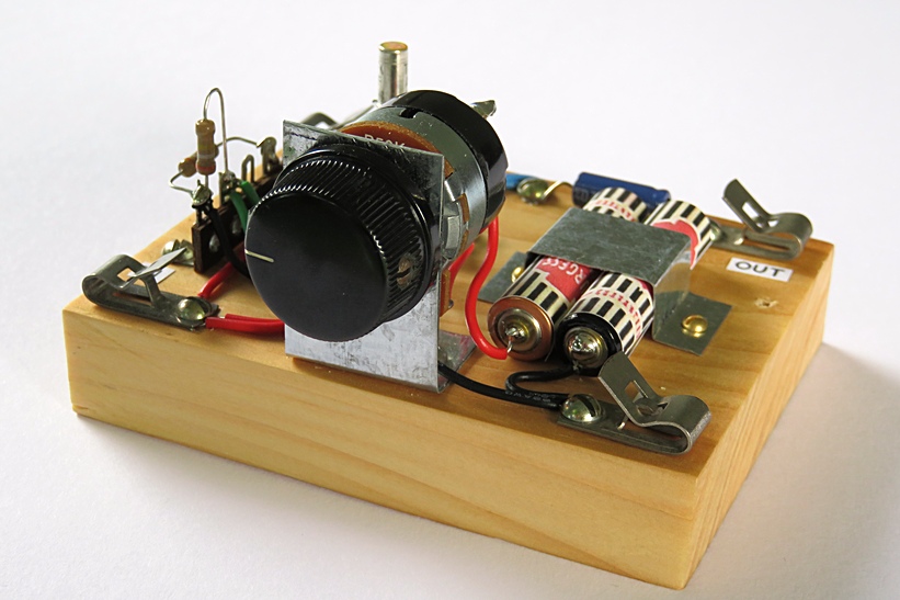
Here's the completed amplifier. Now we have a
more serious rendition. We can turn it on and off, control
the volume and the 3 volts DC no longer passes through the
headphones. |
|
|
|
|
|
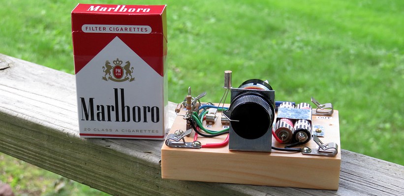
Here's an ad for cigarettes!! Since they
aren't allowed on TV, I thought I'd put one here. Come to
where the flavor is, come to Marlboro country.
Actually
it's just there as a reference to show the size of the
amplifier. |
|
|
|
|
|
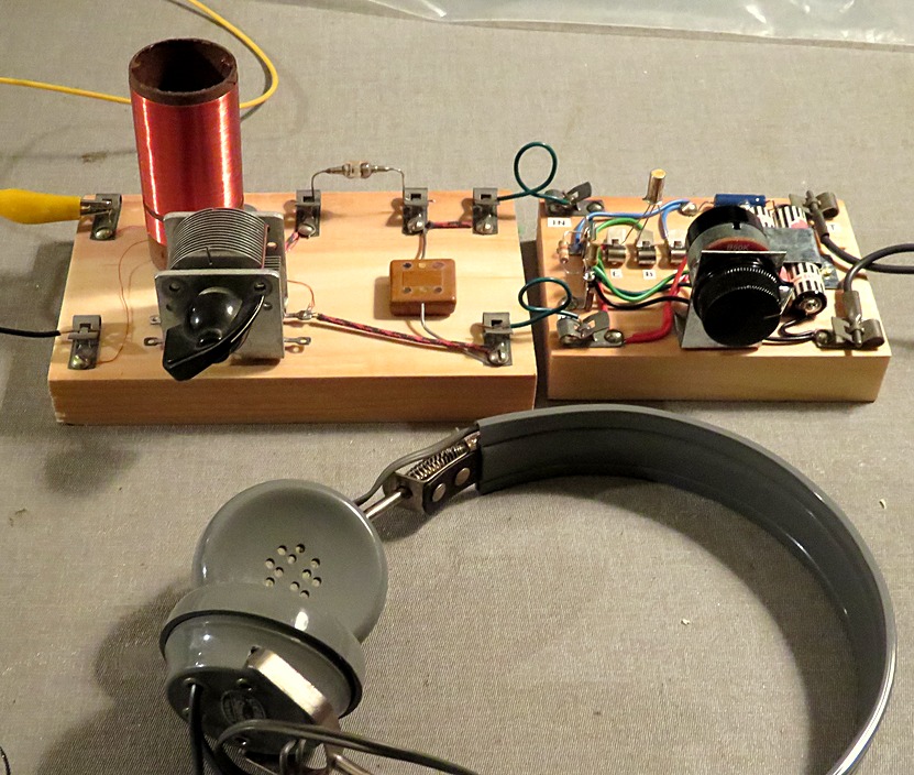
I had hoped the amplifier would drive a
speaker, but it does not. It's designed for high impedance
headphones. The crystal set in this photo is from
the same book, "The Boys Second Book of Radio and
Electronics." |
|
|
|
|
Epilog |
|
|
|
|
Six months after making the Morgan Amplifier
I came across a cool YouTube video. The video showed a real
set of Burgess No. 7 dry cells. It seems my reproductions
are not up to snuff. I didn't notice that Morgan had
rendered the red tops of the battery labels in his drawings.
The good news is you will probably enjoy the
video. |
|
|
|
|
|
|
|
Eventually, the Duracell batteries leaked.
The expiration date was still two years away, but those
things leak in the package before you even buy them. Since
the Burgess skins were ruined I made new ones using Ray-O-Vac
batteries. Also, I had obtained a real CK722 transistor and
some vintage battery holders. |
|
|
|
|
|
|
The amp was built again with the correct
transistor and the red tops on the battery labels. It even has
the exact screws Morgan says to use. |
|
|
|
|
|
|
Now it matches the picture in the book! |
|
|
|
|
|