|
|
|
|
|
|
| |
 |
|
| |
-
Elmer Osterhoudt
Modern Radio Laboratories
|
|
|
|
|
|
|
|
|
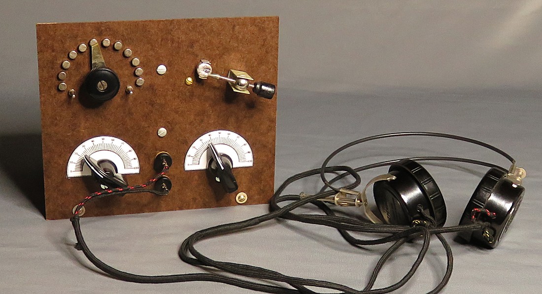
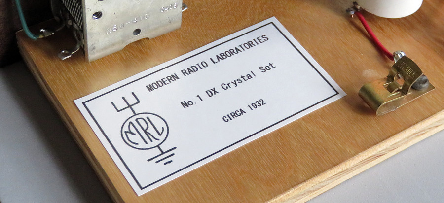
This is a Modern Radio Laboratories No.1
Crystal Set that was built in 2020. The circuit was
developed in 1932 by Elmer Osterhoudt. |
|
|
|
|
The trademark "Modern Radio Laboratories" was
granted on
December 15, 1932.
The first MRL product was a "blue print" to build this
radio. |
|
|
|
|
|
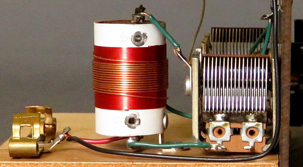
Close-up of the wave trap. The coil and
variable capacitor combination can eliminate a strong
interfering signal. |
|
|
|
|
|
|
|
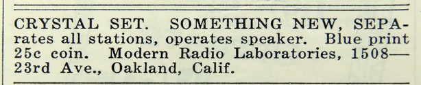
The very first MRL advertisement. This
appeared in the February 1933 issue of "Short Wave Craft."
For 25¢ you received a "blue
print" of the MRL No. 1 crystal radio. The "blue print" was
actually just a mimeograph copy of the plan.
It doesn't sound like you got much for 25¢, especially when
you consider it was worth over five dollars
today, but people must have sent in their quarters because it
started a company that lasted for over half a century. As a
matter of fact, in 1968 Elmer related that after he placed
the ad above, the floor was covered with letters with 25¢ in
them. This was in the middle of The Great Depression! |
|
|
|
|
While researching Elmer Osterhoudt and
MRL, it occurred to me there may be no one alive today who
has ever seen an MRL No. 1 Crystal Set. There are surviving
examples of the No. 2 set, which came as a kit, and was sold
until 1986 when Elmer passed away. It was resurrected in
the 1990s by Paul Nelson, who took over MRL. However, the
No. 1 set was never sold as a kit.
The only way anyone was going to see one was to
build one! |
|
|
|
|
|
|
|
|
|
| |
|
|
|
|
| |
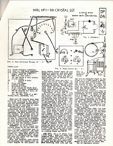
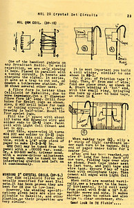
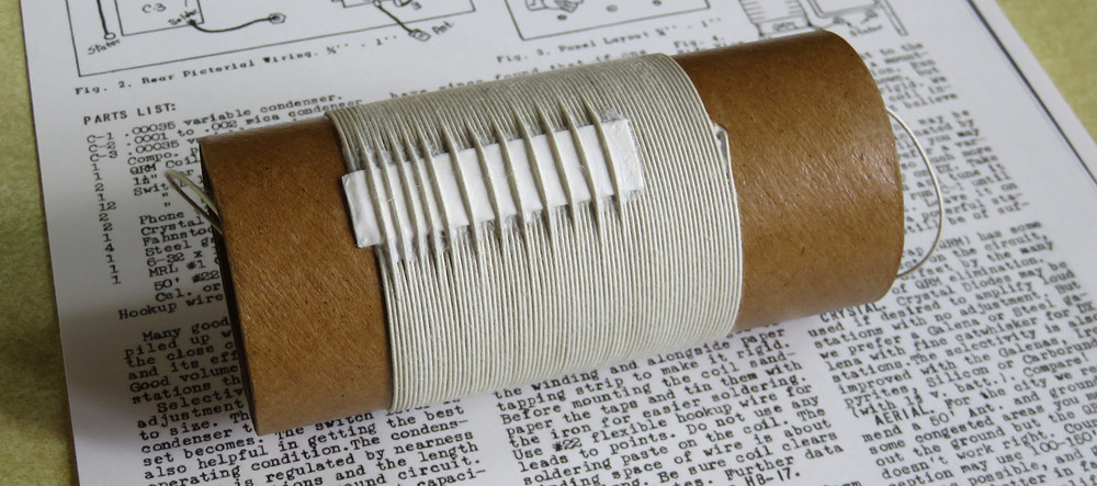
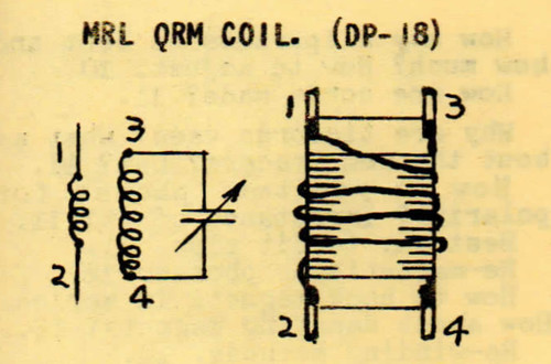
DP-26 MRL No. 1 Crystal Set |
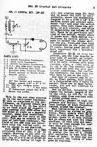
HB-17 MRL No. 1 Crystal Set |
HB-17 - making the coil for the
trap |
|
|
|
|
| The original "blue print" is lost
to history, but fortunately Elmer Osterhoudt
published the plans in two different documents
several decades later. On the left is "Detail Print"
number 26. In the center is a version of DP-26 found
in Hand Book 17. On the right is the back page of
HB-17, showing how to make the MRL "QRM" coil. Click
on the thumbnails to view the plans. |
|
|
|
|
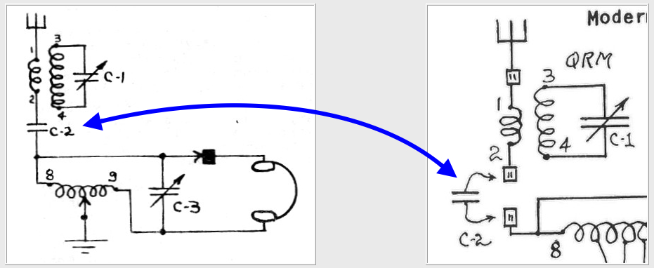 |
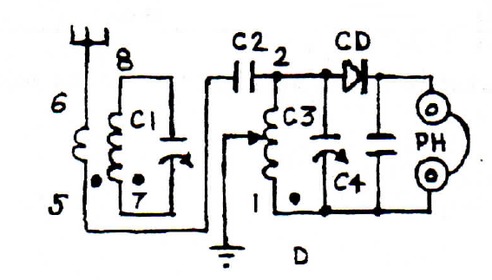
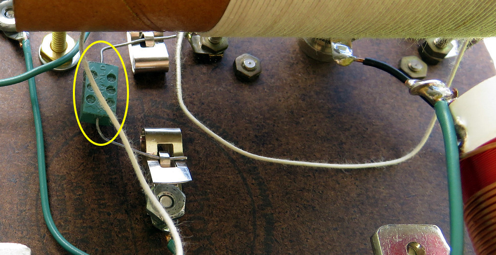
Elmer said the value of C2 is
important and is determined by your particular
antenna. On the right it shows that Fahnestock clips
are used so you can swap out different values.
The circuit is unusual. Normally in a circuit like
this, the switch on the coil would short out a
section of the coil. This circuit uses the full
length of the coil at all times, but connects it to
ground somewhere in the middle, depending on which
tap you select.
Notice the numbers 8 and 9. These are explained
further down, under the photo of the coil. |
|
|
|
|
|
|
|
Turning the main coil and removing the QRM
filter in the schematic shows what a simple design this is. |
|
|
|
|
|
|
The same circuit from a MIDCO catalog in the
1980s. The kit from MIDCO cost $89.00 at the time. |
|
|
|
|
|
|
|
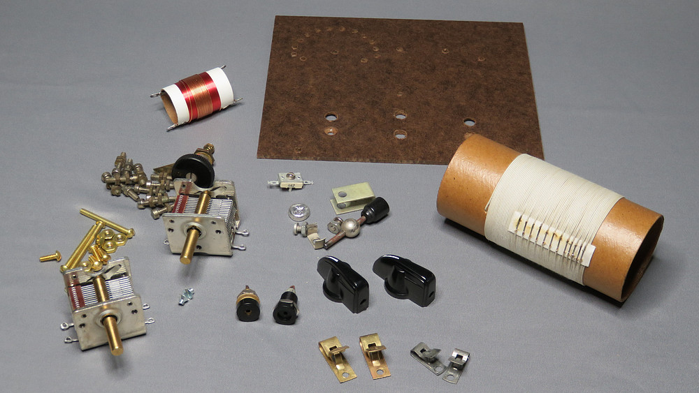
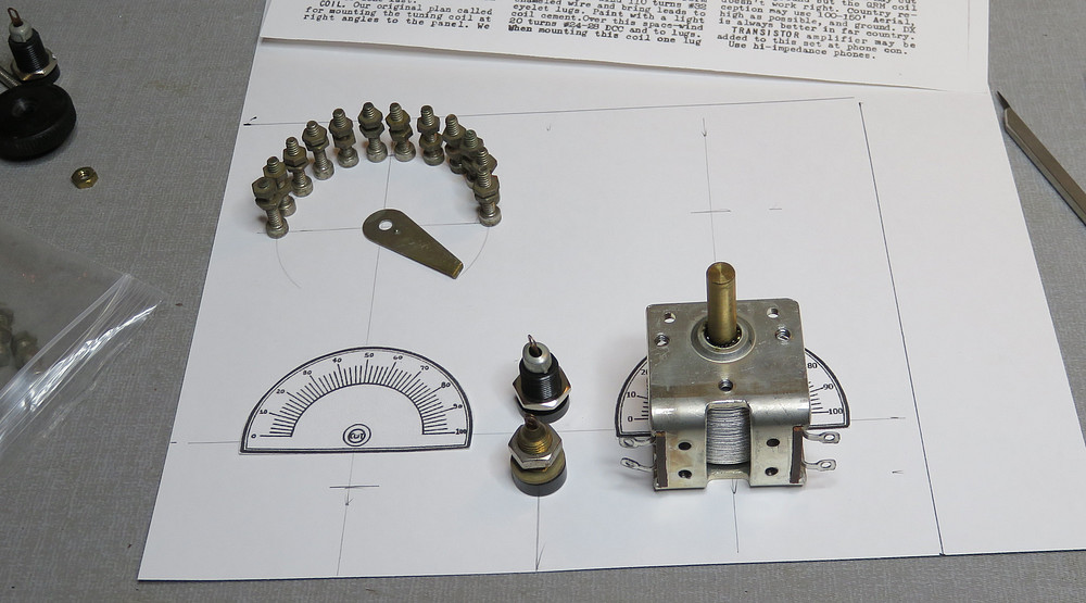
If MRL sold the No.1 crystal set
as a kit (as they did the No. 2 crystal set), it would
look something like this. You would get all these
parts and full instructions for about $1.80. The
coils would be pre-wound and the front panel would
have all the holes already drilled in it.
The $1.80 price seems low, but I derived it like
this: The MRL No.2 crystal set has almost the exact
parts count as the No.1, but without the "QRM" coil.
The No.2 kit sold for $5 in 1973. $5 in 1973 was
worth $1.54 in 1933. Throw in the QRM coil for $0.25
and you have $1.79!
Well, it's 2020. There was never a No.1 crystal set
kit and Elmer Osterhoudt isn't around to order these
parts from. It took weeks to gather these parts and
they cost over $100.00. If I didn't already have the
crystal and cat whisker detector, it would have been
an additional $55. (They used to cost 19 cents.) The
most difficult item to acquire was the vintage cloth
covered wire, which came from ebay.
The switch points and lever were purchased in 2018 from
Gary Schneider (RIP) on his website, "Play Things Of
Past Medina, Ohio" (or "Playthings of the Past" as
people called it). |
|
|
|
|
|
|
|
|
|
|
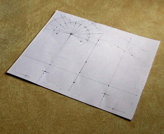
Making a template for the front panel. |
|
|
|
|
Making the template for the front panel
took longer then I thought. The spacing for the switch
points had to be more or less perfect. (It was probably
perfect on the template but was less than
perfect on the panel, due to my drilling. I had to enlarge two of the holes to slightly
move two switch points.)
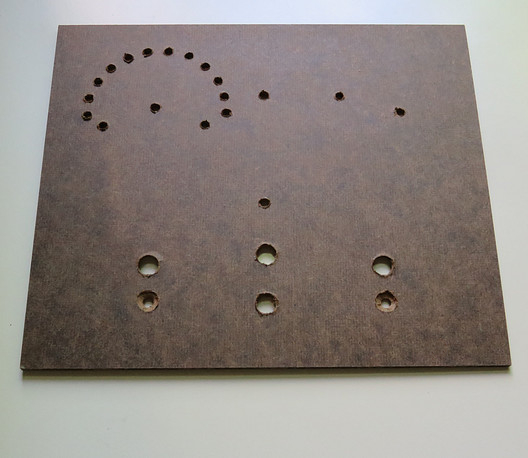
In all of Elmer's prolific writings, he always referred to
the panel material as "Compo." The list of parts for
this set says to use 1 Compo. panel 1/8" x 6" x 7". It took
quite a bit of looking to discover "Compo." is Masonite.
Apparently, "Compo." is short for "composition board."
1/8" Masonite is difficult to find for some reason, unless
you want to buy a sheet 8 feet long! This panel is an
"Ampersand Museum Series Hardbord Panel." (Notice the
spelling of "hardbord.") I got it from "Jerry's Artarama," in a
pack of three. They are 5" x 7" and came in a giant box. The
box was so big I wondered what the heck I had ordered when
I saw it. They sure were packed well!
UPDATE! Thanks to fellow MRL fan Vic Rodriguez, a perfect
layout of the front panel is available in .PDF format
here. |
|
|
|
|
|
|
|
|
|
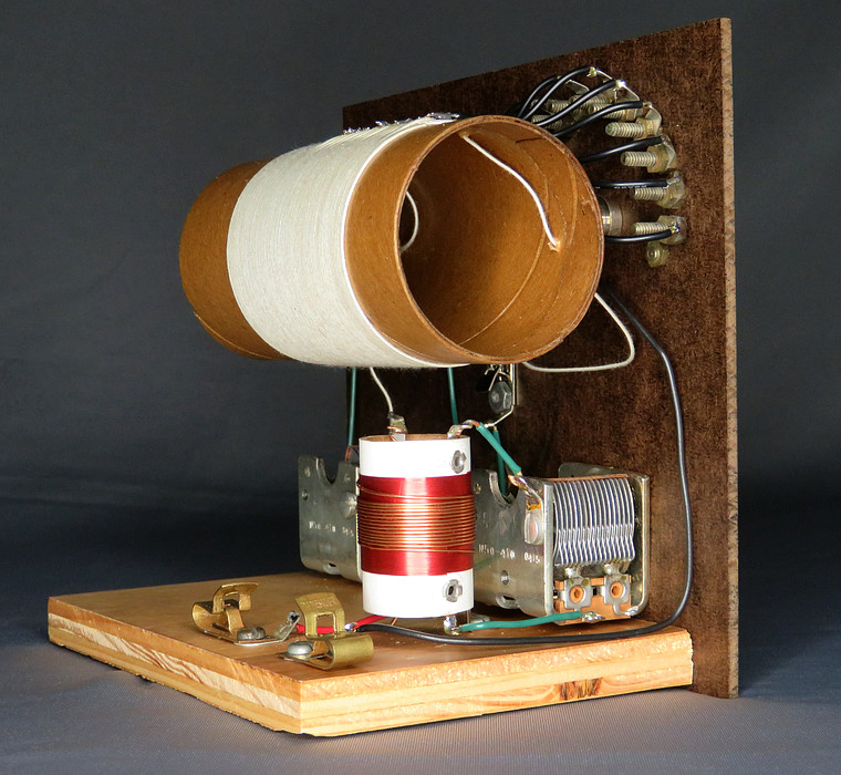
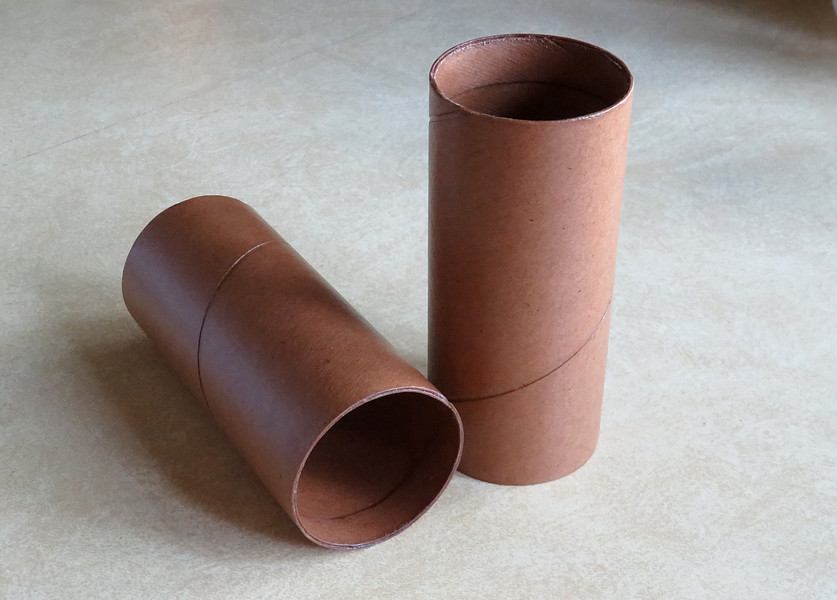
| The coil forms had to be of a
thin material, as any interaction of the coil with
the form affects the performance of a crystal set in
a negative way. These are made from a thin wrapping
paper tube, 2 inches in diameter. The ends were
reinforced and they were given three coats of
polyurethane to strengthen them. |
|
|
|
|
|
The coil was wound by hand and tapped in the
appropriate places, per the instructions.
Elmer said to use "coil dope" to hold the ends together. I
used Elmer's Glue-All. Different Elmer, same name.
NOTE: The schematic shows numbers 8 and 9. In the
photo above, 8 would be on the left, 9 on the right. |
|
|
|
|
|
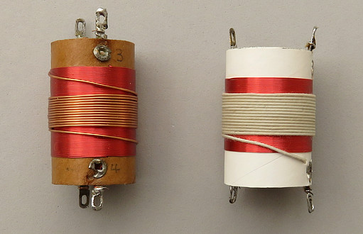
| Listing for the two coils, from
page F-6 of the MRL catalog. It's actually called an
"8-9" coil. This is one of those MRL mysteries. 1,
2, 3 and 4 are the connections to the QRM coil. What
happened to 5, 6 and 7? We could possibly find out
if an original "Blueprint" can be found. |
|
|
|
|
|
|
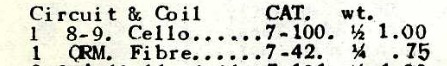
I don't know what the correct method is to
remove the cotton cover from the wire, but I picked it off
with a utility knife and tweezers.
Under the cotton, the wire is coated with enamel. The enamel
was scraped off, then the wire was tinned with solder. |
|
|
|
|
|
Sloppy solder connections. |
|
|
|
|
|
|
|
|
| The QRM coil. QRM is "man-made
interference." This coil is used with the left dial on the
front panel to null or trap a station that is
causing interference. It would be interesting to see
how the original "blue print" described the making
of this, since there was no "MRL QRM COIL" for sale
at the time. If you make
your own, both coil windings go in the same
direction, a fact that Elmer never mentioned. If you
want to use those rivet type solder lugs, they are
still available at MRL to this very day, which is
where I got them.
MRL WEBSITE
A fan of MRL named Victor Rodriguez
pointed out that in some publications Elmer says to
wind the large coil with 110 turns, and other times
he said to use 105 turns. He said to use 15 turns
space wound for the smaller coil, and he also said
to use 20 turns close wound. He said to use cloth
covered wire, but his later coils had enamel
covered wire. The fact is, any of these combinations
will work. |
|
|
|
|
|
|
|
|
|
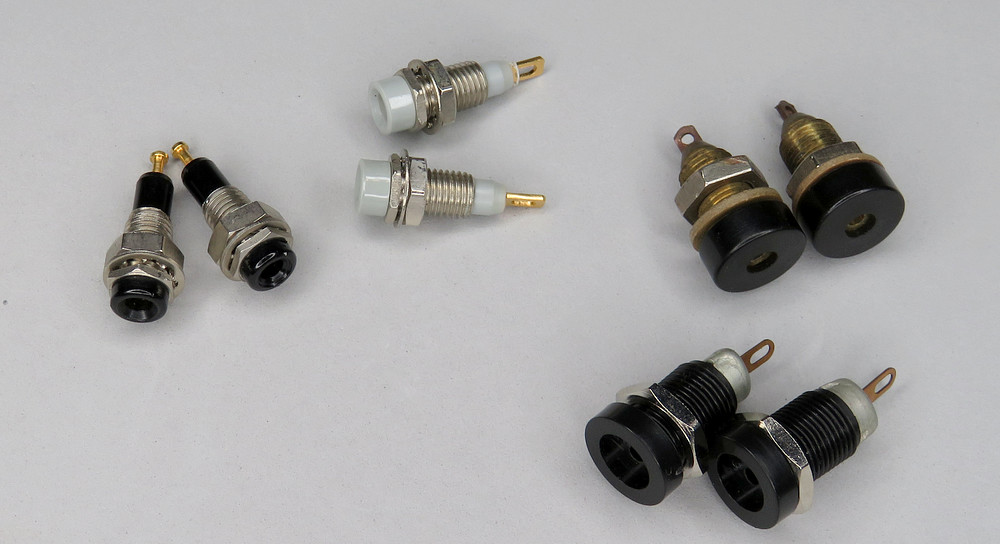
| Headphone jacks. Every MRL radio
I've ever seen uses the type on the left. They came
in blue, yellow, orange, red, gray and black.
However, I can't help but think these are post WWII
and weren't available in 1932. I opted to go with
the ones top-right. The brass shanks tell me they
are really old. |
|
|
|
|
|
|
|
|
|
|
|
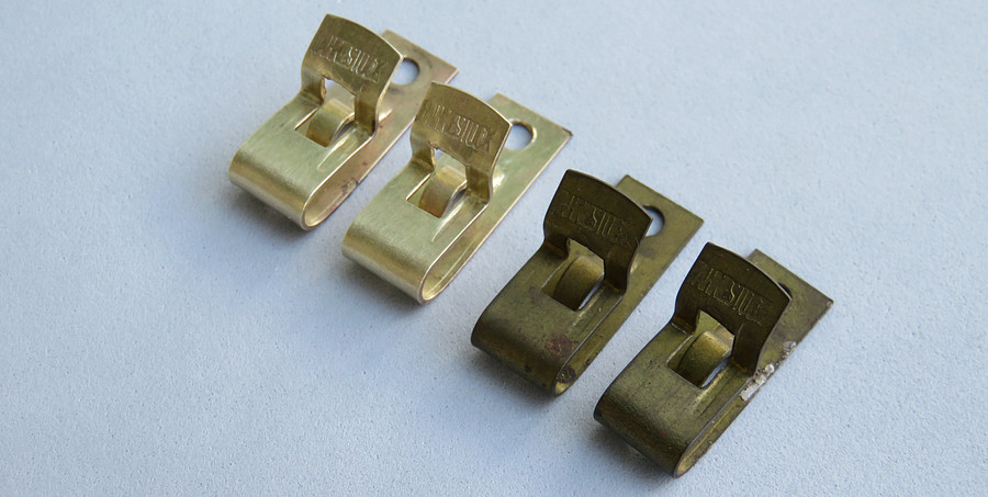
| Elmer
said to use 1 inch Fahnestock clips for the antenna and
ground. Do you know hard it is to find 1 inch Fahnestock
clips?? Why do they need to be an inch? I found four
of them. I polished two of them so they would look
new. |
|
|
|
|
|
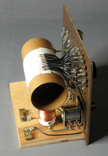
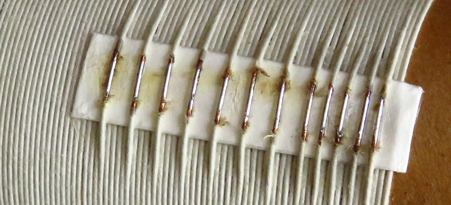
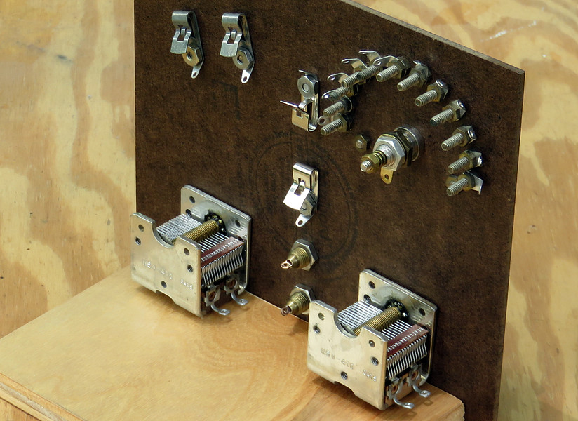
The rear before wiring the set. The
instructions say to wire it first, then add the main coil.
One concession I had to make was to use modern variable
capacitors. They actually look very much like vintage ones,
but a little smaller.
The is no mention of a wooden base in the instructions.
Upper-left, two Fahnestock clips are there to bypass the
cat-whisker detector with a diode if needed. They weren't
needed. |
|
|
|
|
|
|
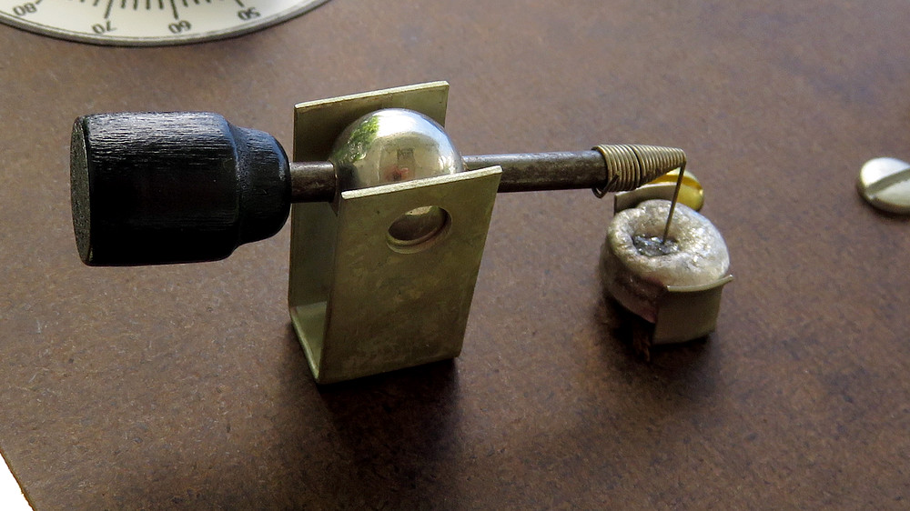
The Philmore crystal detector. I
wasn't sure if they were made in 1932, and didn't
know if the wooden knob was historically accurate
for an older version.
It turns out that Philmore had been around since
1921, and even though some versions had a Bakelite
knob, the wooden version is fine. |
|
|
|
|
|
|
|
|
|
|
|
|
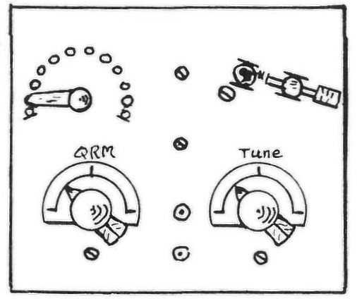
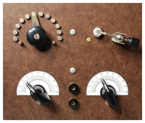
The drawing of the front panel compared to the actual
front panel. The drawing is from DP-26. |
|
|
|
|
|
|
|
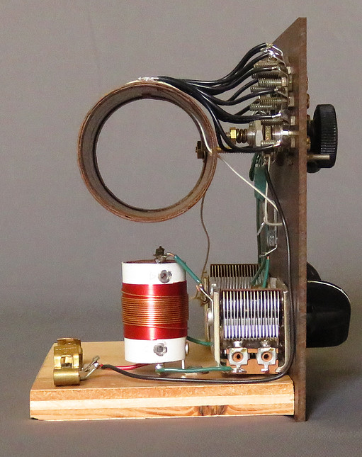
| Here is capacitor "C2" mounted in
its Fahnestock clips. Elmer has this positioned behind the coil, and
it is difficult to reach. Once you select
the right value you don't have to touch it again,
but it's frustrating to swap out. |
|
|
|
|
|
|
|
How well does it work? Below is a video
of a quick test. It was done in the morning of July 2, 2020. The
location is about 15 miles NE of Philadelphia, PA. It logged
four whole stations!
Actually, I think it works very well for a simple crystal
radio. It wasn't designed to be selective, yet the stations
are fairly spread out across the dial. |
|
|
|
|
|
|
|
|
|
|
View here or on YouTube:
https://youtu.be/0u6qxIfAmWg |
|
| |
|
|
| The radio needed a label to
identify it. I was going to make an elaborate one, but Elmer would
never have approved it. |
| |
|
| Next, a MRL number 2-A set! |
| |
|
|
|
|