|
|
|
|
|
|
MRL® #18
Selective Diode-Crystal Set (replica)
also known as the
"MRL QRM COIL TRANSISTOR SET"
|
|
|
|
|
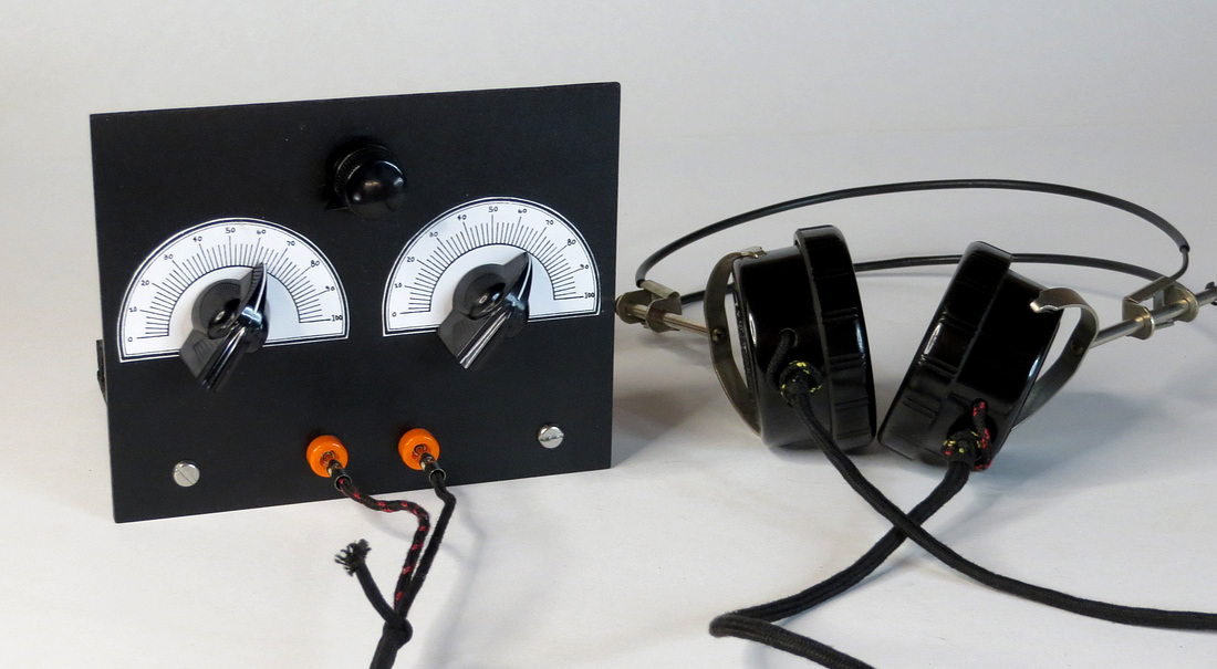
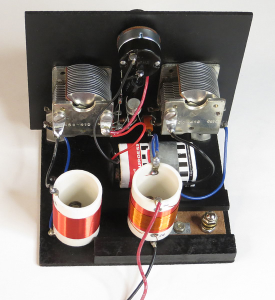
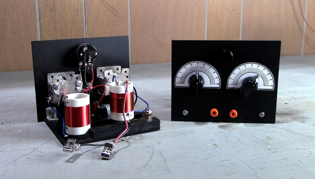
Rear View.
The No.18 is an amplified crystal radio with variable selectivity. |
Originally developed and sold as a kit by Elmer Osterhoudt
of Modern Radio Laboratories, the MRL QRM Coil
Transistor Set first became available in the late 1950s
or early 1960s. This replica was built in September of 2025.
The original price isn't known, but in 1963 the kit sold for
$7.95, which is equivalent to about $83.00 in 2025.
Considering the cost of those variable capacitors, that's
about what it cost to build this. Elmer always did have a
knack for calculating inflation, and he's still correct 62
years later.
|
|
|
|
|
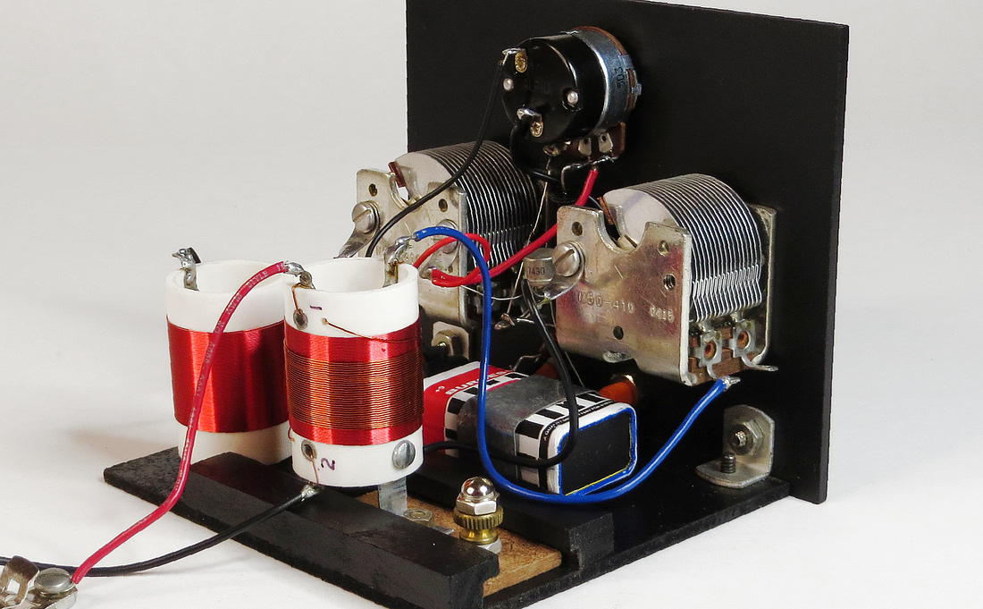
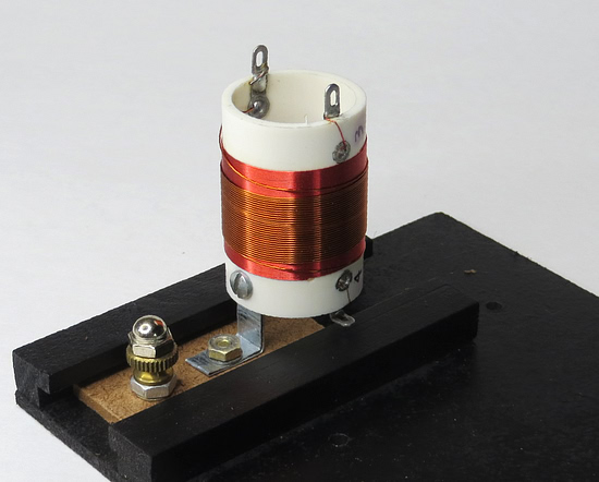
Variable selectivity is accomplished by adjusting the
position of the
primary coil, shown here in the center of the photo. |
|
|
|
|
|
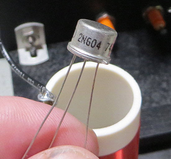
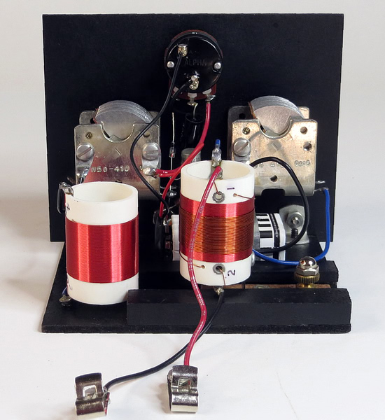
Rear View. The radio uses a 1N34A crystal diode
followed by a one transistor amplifier. |
|
|
|
|
|
The reproduction was made by copying this
MRL #18 kit from 1982, and using the instructions. |
|
|
|
| |
|
|
| Someone's
fingerprints reacted with the cadmium plating on this
capacitor. Could they be Elmer Osterhoudt's fingerprints? |
|
| |
|
|
|
Detail Print 18. Everything you need to know
about building the set is on a single sheet of paper. LINK |
|
| |
|
|
|
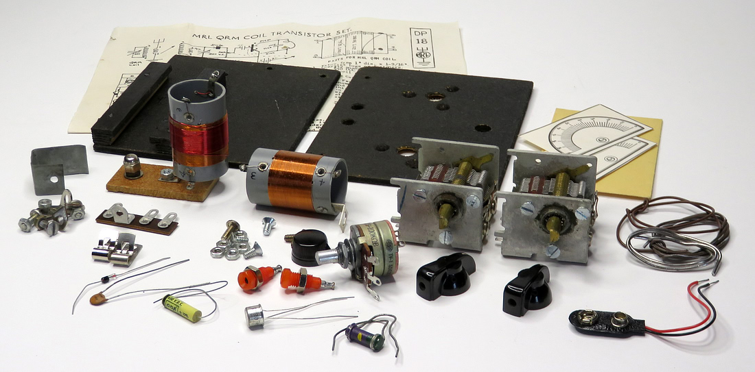
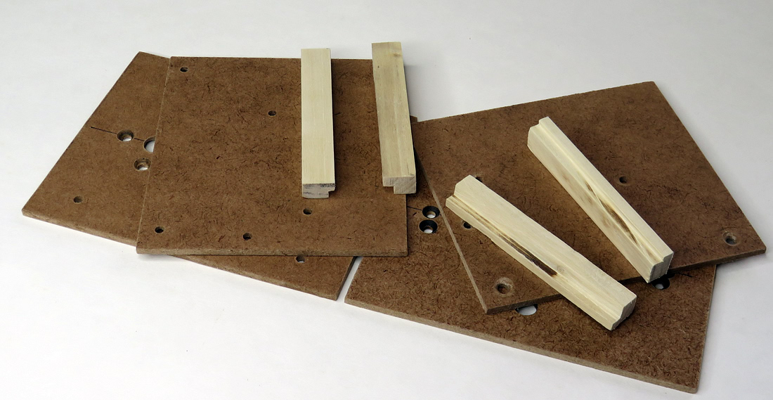
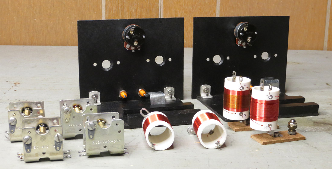
First things first, here are the bases, panels and wooden parts to build two reproductions.
|
|
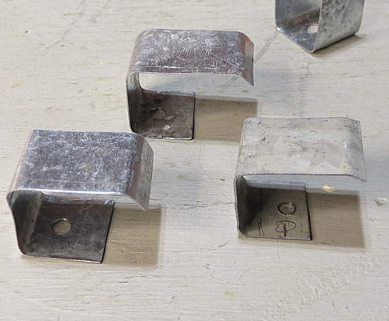
| "ALL YOUR BASE
ARE BELONG TO US" |
| |
|
| |
|
|
|
|
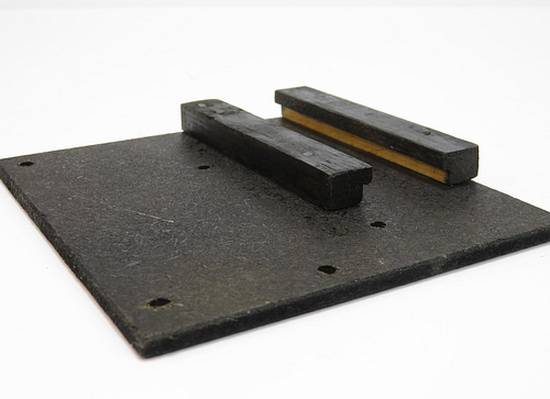
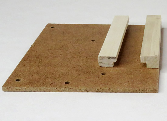
| The base
made by Elmer Osterhoudt is on the left. |
|
| |
|
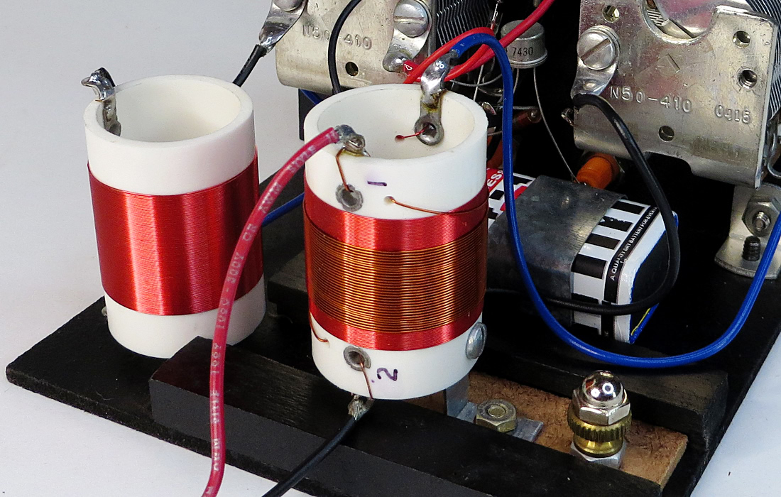
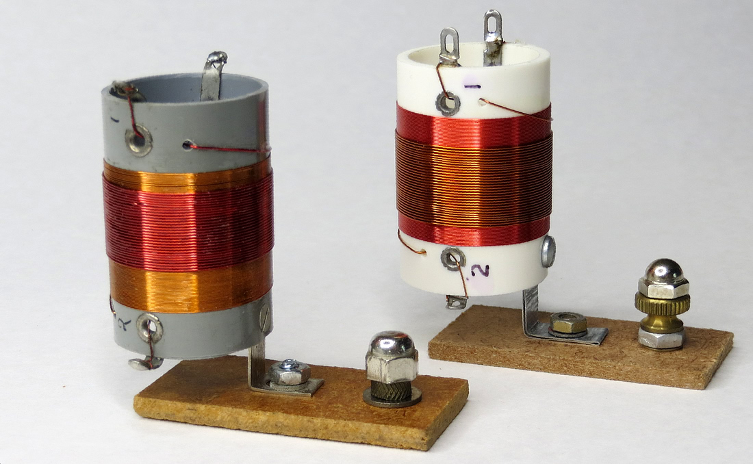
PRIMARY COIL |
| |
|
|
MRL primary coil on the left,
reproduction on the right.
These were sold as "QRM"
coils, ergo the name of the set. QRM coils are used to
filter out unwanted interference, but have a different
function in this set. |
|
| |
|
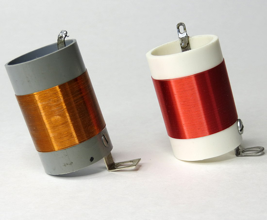
PRIMARY COIL SLIDER |
| |
| |
|
|
|
|
| MRL QRM coil in its track on the left, reproduction
on the right. |
|
| |
|
SECONDARY COIL AND BATTERY HOLDER |
| |
| |
|
|
|
|
|
MRL made secondary coil on the left.
The original MRL battery holder on the right has a pencil mark near
the mounting hole. |
|
| |
|
|
|
Elmer's battery holder positions
the 9 volt battery flat. He made a second type that holds
the battery on its edge. |
|
| |
|
FRONT PANEL |
| |
|
|
|
|
Two drilled and painted reproduction front panels drying. |
|
|
|
|
|
|
|
|
Enough parts for two radios. |
|
|
|
|
|
|
Two sets in progress. |
|
|
|
|
THE TRANSISTOR |
|
|
|
|
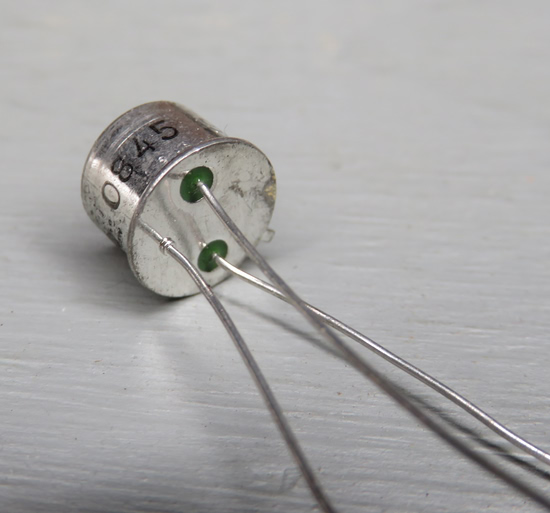
| On the left is the Germanium
transistor supplied by Elmer with the kit. It was
made by General Electric, but trying to find what it
was by using the number on the side (0845 952) was fruitless.
In the MRL catalog it is simply listed as "Germanium
Transistor." A test showed it had a gain of 93. On the right is a vintage Germanium transistor
purchased on ebay. The criteria was its appearance,
since almost any Germanium transistor will work in this
circuit. |
|
|
|
|
|
GE transistor sold by MRL. How old is it?
Transistors for hobbyists from GE with silver cases didn't
appear till the 1960s. This transistor came from MRL in
1982, but the year Elmer purchased it will never be known. |
|
|
|
|
|
|
|
|
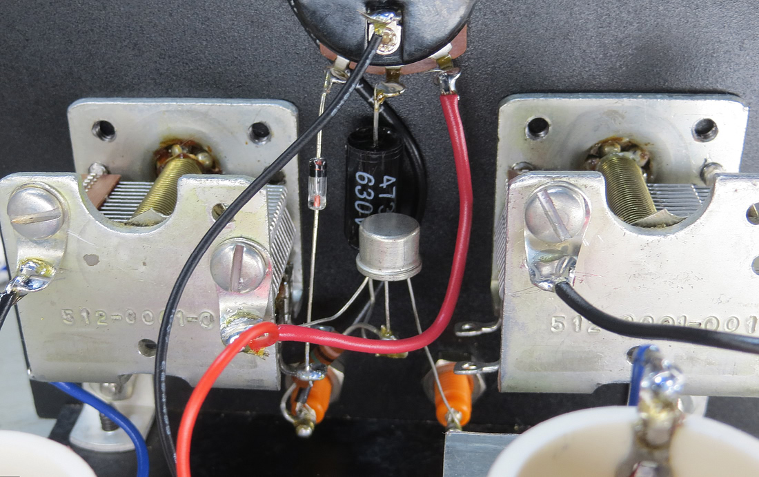
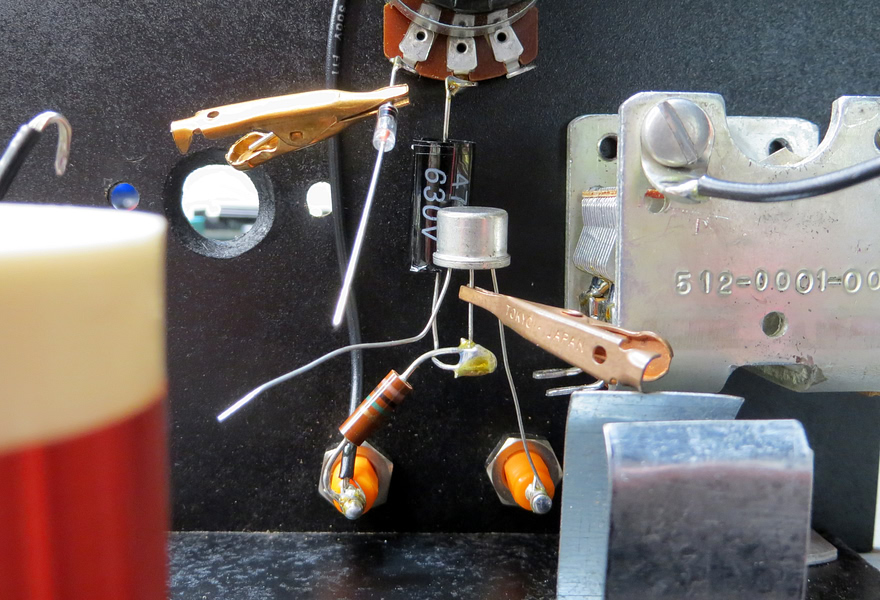
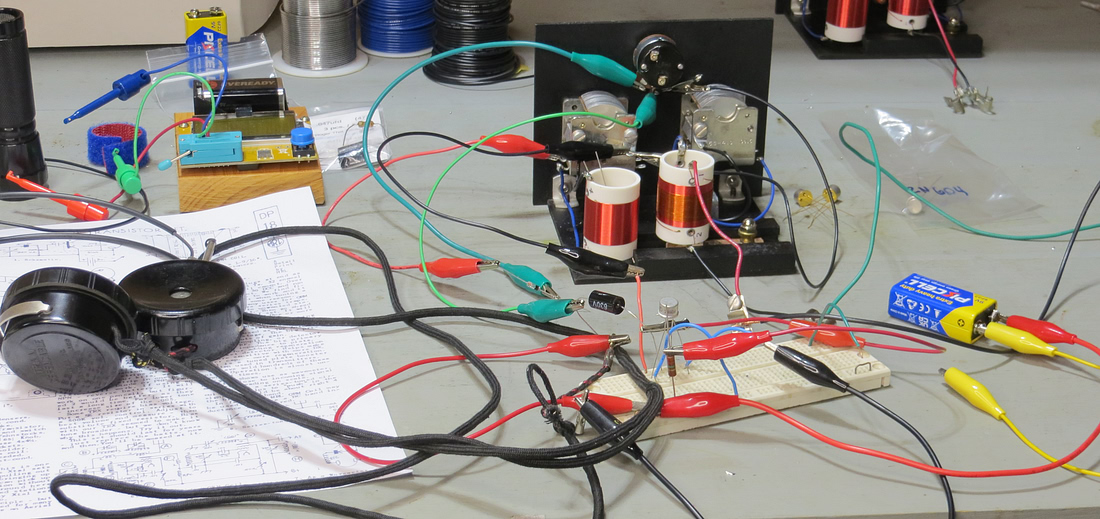
| Small alligator clips were used
to heat sink the transistor and
diode while soldering.
Notice the 1 megohm resistor. On the schematic it is
shown with a dotted line and the word "Bias." This
was needed for proper operation of the transistor. |
|
|
|
|
|
|
| To find the
correct value bias resistor, the amplifier was built
on a terminal board (it only has three parts!) and
various resistors were substituted. This resistor is
placed between the base of the transistor and the
negative battery terminal. Elmer said to do this in
the instructions, since different transistors will
need different bias resistors. Some don't need any
at all. |
|
|
|
|
|
|
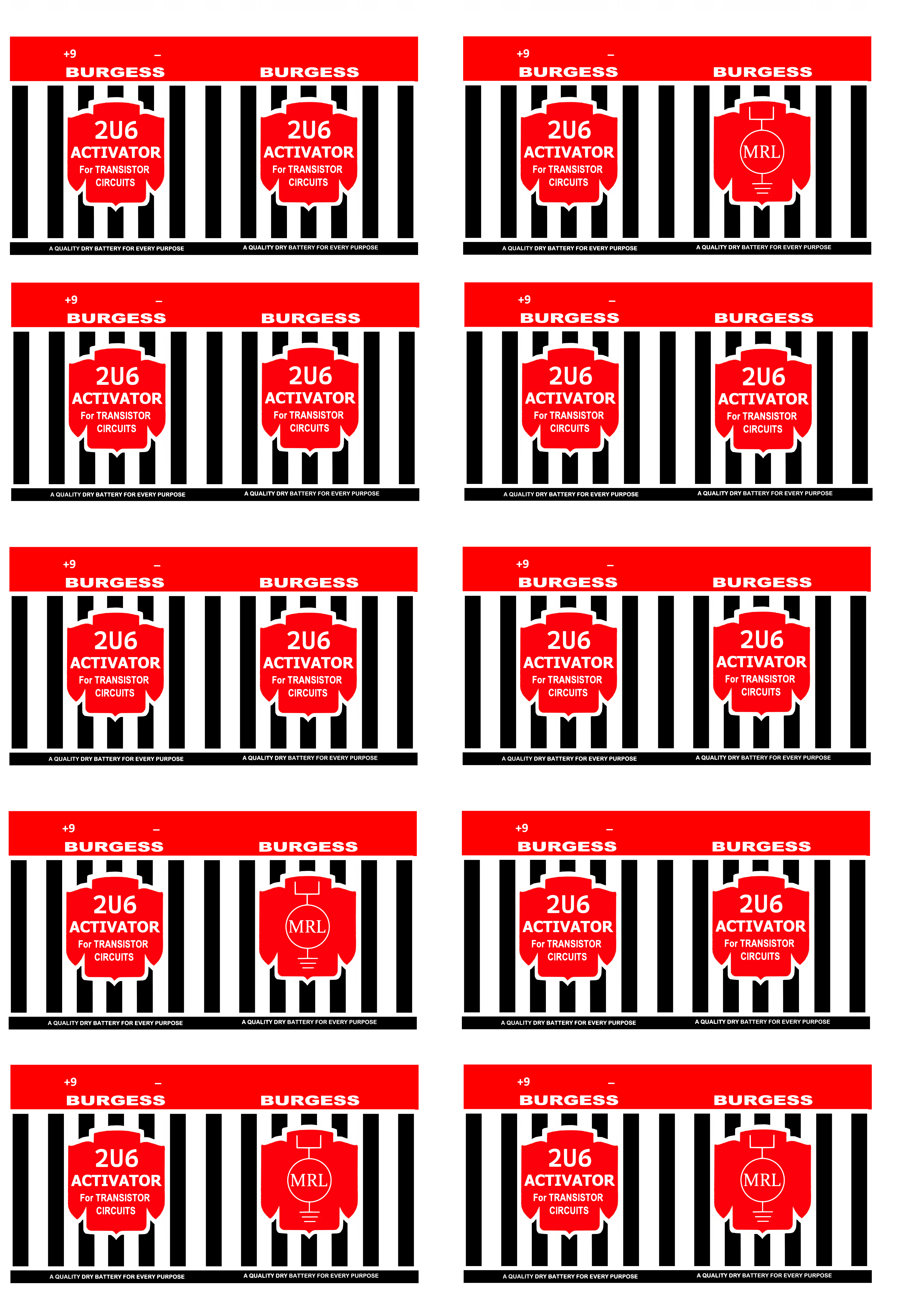
| Elmer sold Burgess batteries
through the MRL catalog. They haven't been made
since 1989 so a modern 9 volt battery will have to
be skinned with a decal. If you need a
vintage battery, click on the photo for the graphic
file. (NOTE: paint the battery white first. Cut the
decals in half and skin the front and back of the
battery separately.) |
|
|
|
|
|
|
|
Two views of the completed radio. |
|
|
|
|
|
|
This set is an excellent performer. If I could only
build one crystal set, this would be it. See it on YouTube
HERE. |
|
|
|
|
|
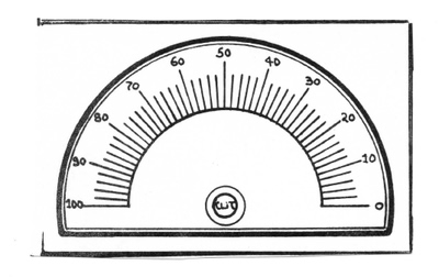
| Elmer
never included a picture of a dial scale in his
plans and Detail Prints. The dial scales came with a kit or
could be purchased from the catalog for 5¢.
Let's fix that right now! Click on the label above for a .PDF
file of the correct size and type of dial scales for
many MRL sets. |
|
|
|
|
| |
|
|
| |