|
|
|
|
|
|
SWITCH POINTS |
|
|
|
|
|
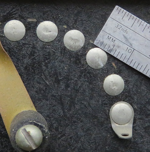
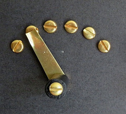
| MRL switch points were
approx 5.5mm in diameter, probably 3/16". Using a
piece of black poster board, I was able to try different
screw types to replicate the rivets Elmer Osterhoudt used.
On the right are "Chicago screws." These look pretty cool,
but not for this radio. They're a little too big, but will
look great in another radio. |
|
|
|
|
|
|
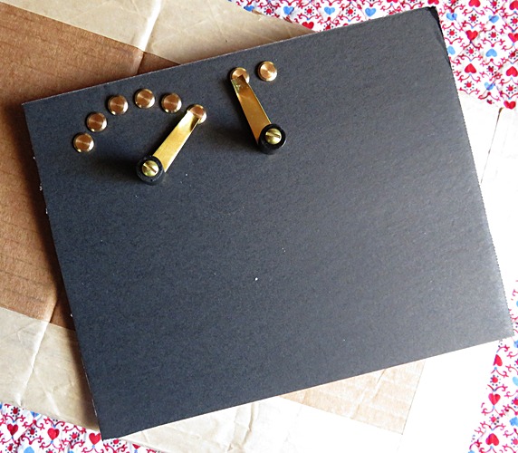
A closer view of the Chicago screws. On the
right are 6-32 flat head screws. |
|
|
|
|
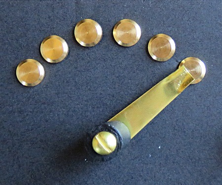
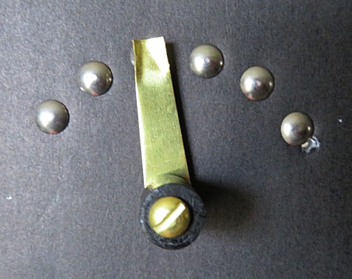
I also tried 6-32 brass flathead screws,
but they still looked like screws! Then a fellow MRL fan named Vic Rodriguez
wrote to me and said, "Mike try these threaded rivets." and
sent me a link to a place that has parts to restore vintage
cars. They looked great! (This photo shows them on the
poster board.)
Naturally, I selected the wrong ones the first time and had
to wait another week for the correct ones to arrive. If
you're interested, the part number is NUT250, 3/4" truss
head.
LINK. |
|
|
|
|
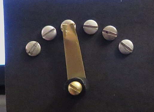
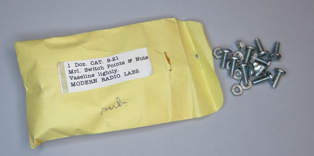
If you're wondering where I got the idea
to use screws, take a look at this. When actual switch
points became impossible to get, MRL
substituted 6-32 flathead screws. These are from 1984.
NOTE: The label on the envelope is obviously
an address label, but who typed it? The address label
company? MRL is spelled "Mrl." (with a period) as in "Mr." or
"Mrs." Was this addressed to Mister Switch Points
(and family)? |
|
|
|
|
|
|
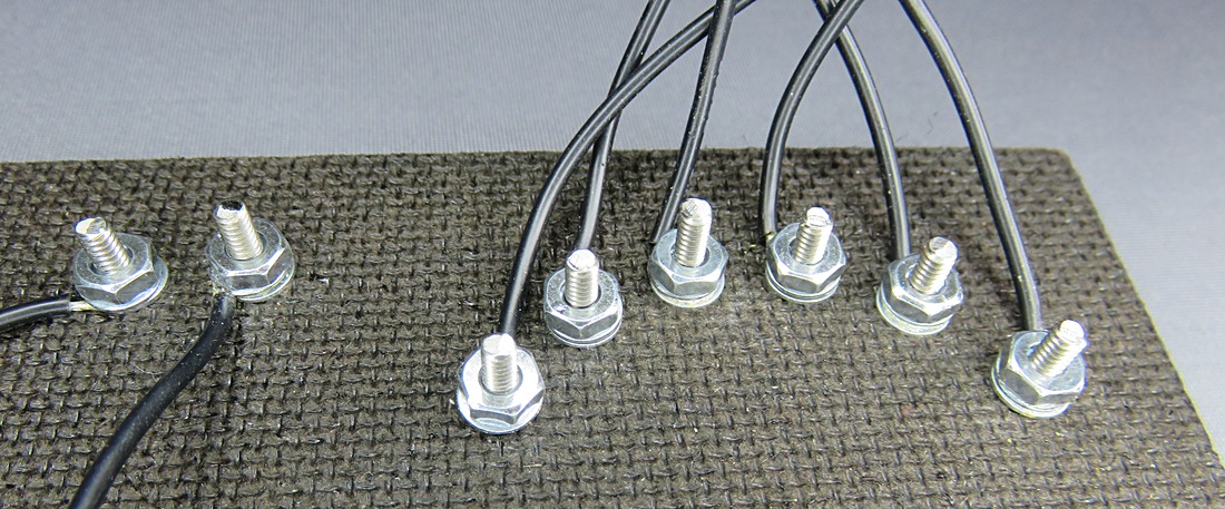
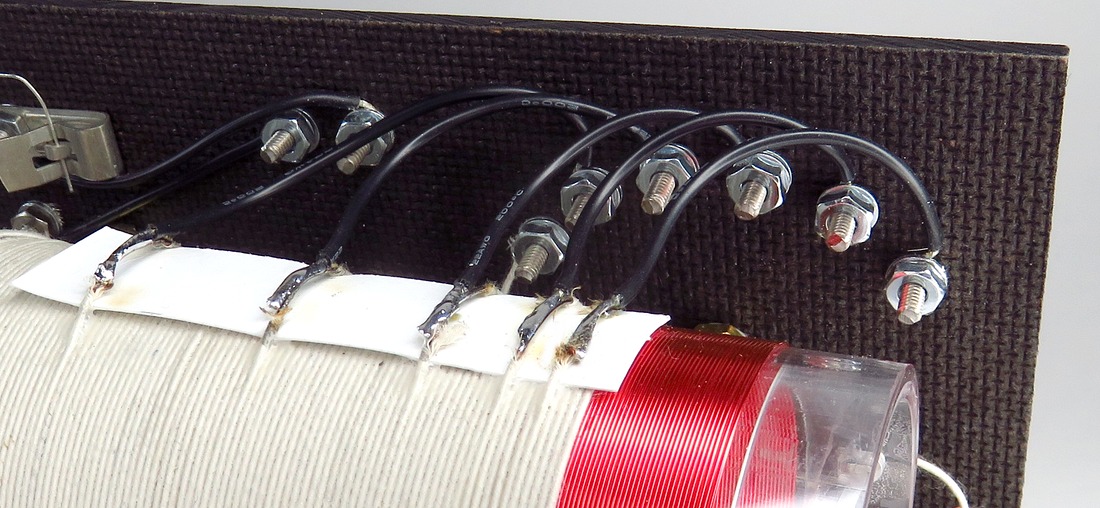
Here are the connections on the back of the front
panel. I had to cut the length of the screws down.
Elmer would never have done it this way. This is a hundred times
more expensive and time consuming than using actual rivets. |
|
|
|
|
|
The switch points connected to the coil. |
|
|
|
|
|
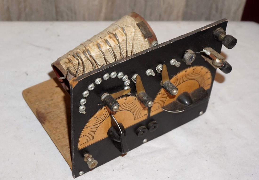
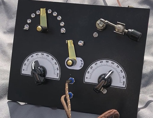
| This MRL radio uses screws as switch
points. This thing looks ancient, and it appears to be a No.
2 with an extra switch. What the extra switch does is a
mystery, but it probably switches in a diode, just like the
No.10. How old is it? The MRL style switches date this to after 1952
and
the screws date it to even later. The coil has fibre rings on
the ends and the wire is cloth covered, dating it to 1975 or
earlier. So the best guess is that it was built between 1965
and 1975. |
|
|
|
|
 |
|
| |
|
|
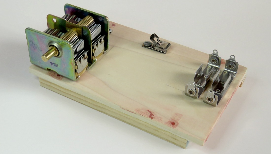
The plans for the No. 10 call for
everything to be mounted on the front panel. I don't
see the logic in this. How do you operate the radio
with nothing to hold it up? You can't lay it on the
table, and you're not going to hold it in your hand,
so it needs a base. In that case, the heavy variable
capacitor and the batteries will be on the base. The
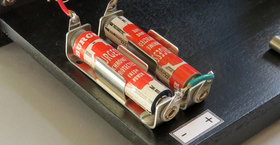
plans call for a 4.3 volt Mercury battery. I used
two AAA batteries. I would have used three, but I
only had two vintage battery holders.
A modern 4.5 volt battery could be used, but the
plans don't show how the battery is connected; it
appears it was soldered in. The heck with that. |
|
|
|
|
| FRONT PANEL |
|
|
| |
|
|
Vic Rodriguez, the guy who sent
me the link for the threaded rivets, mailed me three
blank panels. I told him I don't have an easy way to cut a
panel so it comes out square, and the panels
arrived in the mail a week later, cut to the proper
size. As the Radio Boys would have said in
1922, "He's a regular fellow!"
I made a paper
template, then pushed an ice pick through the paper
and into the panel to mark it. It took hours to make
the template and panel. I kept thinking that if I could buy
the kit, Elmer would have already done all this
work. How did he do it? I bet he had a drill press
and drilled through ten at a time. |
|
|
| |
|
|
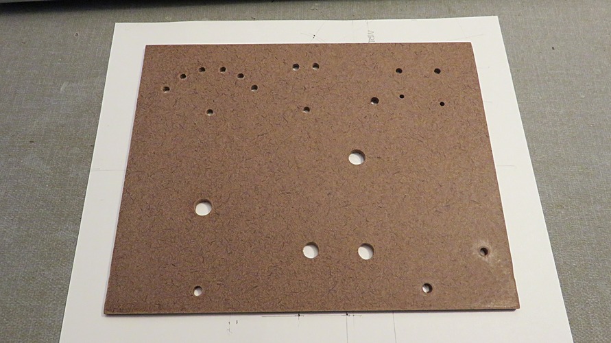
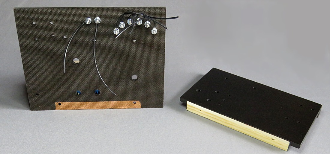
| The panel and base before
assembling. The areas masked from the paint are so wood glue
could be used to strengthen the connection. |
|
| |
|
|
| The coil is mounted last. |
|
| |
|
|
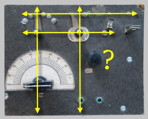
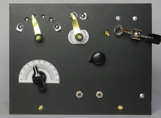
| It seems the original panel was
carefully planned, but the volume control knob is
floating out in the middle of nowhere. It has no
dial scale or label to identify it. By moving the
control down, the panel can be made more
symmetrical. I mulled this over for a day. If I
moved the control, the radio would closely resemble
the MRL No.2 set. On the other hand, this is where
Elmer Osterhoudt thought it should go, for whatever
reason. |
|
| |
| |
|
|
|
| |
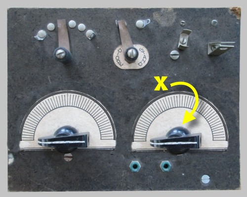
Should I make it look like Vic's MRL No.2
reproduction? |
|
Eventually I figured that
if Elmer thought it should be there, I'll leave it there. |
|
| |
|
|
|
ONE TRANSISTOR AMPLIFIER |
|
|
|
|
|
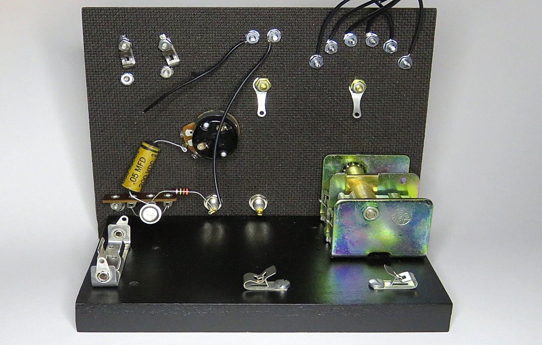
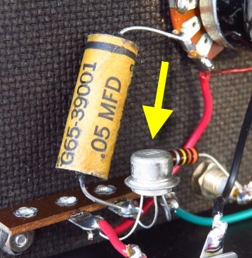
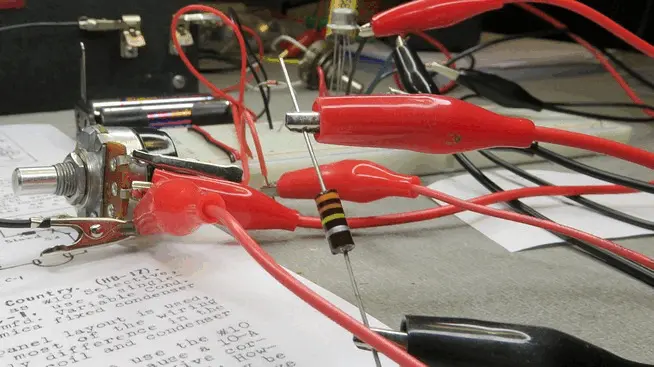
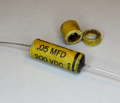
Here's the little one transistor
amplifier. The transistor is a vintage PNP type. In
the plans, Elmer states that a 470K resistor is
supplied with the kit but you may have to change the
value if you use a different transistor, all the way
down to 22K. I had no idea what transistor Elmer
used, or even what transistor I used. How are you
supposed to know which resistor is the correct one? The only way
to find out was to build the circuit and try different values. It turned out
that 330K worked better than 470K for this
particular transistor.
The odd thing is that the amplifier worked with NO
resistor. |
|
|
|
|
|
|
|
This modern capacitor wasn't going to look right, so
it was stuffed into an antique casing. |
|
|
|
|
DIODE |
|
|
|
|
|
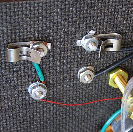
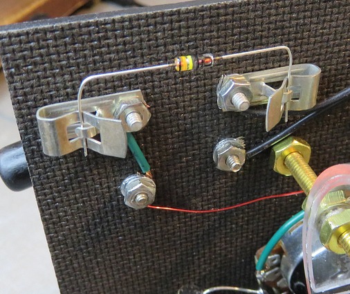
The plans call for 1/2"
Fahnestock clips to mount the diode, which is what I
used, only to notice the screws were too long the
depress the clips. After searching for "the perfect
screws" I gave up and went to 3/4 inch Fahnestock
clips. These are easier to work with, anyway.
The diode is a 1N34A manufactured in March, 1960 by
Kemtron. Kemtron was located in Newburyport, MA, but
not much else is known about the company. The plant
was demolished in 1981. According to The
Transistor Museum, "Kemtron diodes are truly
unique."
So at least the radio has that going for it. |
|
|
|
|
 |
|
How well does it work? Do sparks shoot out of
the headphones? |
|
|
|
|
|
|
|
IT WORKS!
It's a crystal set. It works like a crystal
set.
|
With the one transistor
amplifier, it works like a very good crystal set!
Since this is the "city" version and I have a crappy
antenna, I didn't expect too much, but was pleased
that the few local stations (within 10 miles) came in with very good volume and were easy to
separate from each other. At the upper end of the
coil I heard several shortwave stations, including
CHU Canada on 3.33 MHz.
CHU transmits from Ottawa, Canada and is 450 miles
from this location, which is near Philadelphia, PA. Stating
"I heard it" does not mean it can easily and
reliably be dialed in on a crystal radio. However,
the fact that this crystal set can pick up shortwave
is somewhat amazing. |
|
|
|
|
|
|
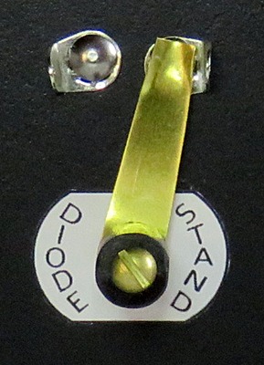
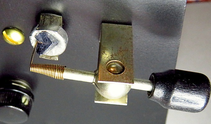
| The control to switch from the
diode to the crystal stand comes in very handy. You
tune a station with the diode, then switch to the
stand and find a "hot spot" on the crystal. The
crystal can sometimes make the radio tune sharper,
or at least seem to. I think it's cool that you can
pick up radio signals with a piece of a mineral, so
I use the stand. |
|
|
|
|
|
|
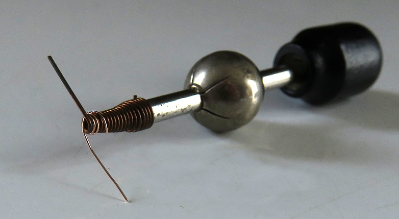
Vic Rodriguez sent me enough fine catwhiskers to last
me the rest of my life. That's "fine" as in thin.
In this photo a piece of fine catwhisker has been wrapped
around the heavy one.
I was halfway done wrapping the wire when I realized
I had stumbled onto a fantastic new invention. The
DUAL CATWHISKER! I gazed at it in awe. It glowed in
my quivering hands like one of Tolkien's Silmarils.
I'll be RICH!! |
|
|
|
|
|
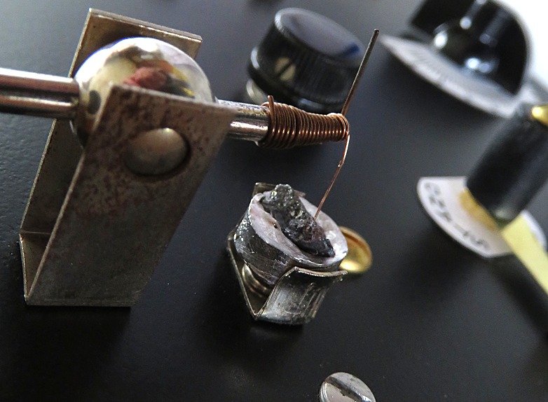
The DUAL CATWHISKER in use. (pat. pending) Yes, I'll be
rich, I tell you!
I'll market it as "Mighty-Fine" since nobody has ever used
that name before. |
|
|
|
|
|
|
MRL sold Burgess Batteries. The AAA batteries were "skinned" to make them look like
Burgess. |
|
Speaking of batteries.... |
|
|
|
| |
|
|
| |